
Generator excitation control system

A technology of excitation control and generator, applied in the direction of control system, control generator, electrical components, etc., can solve problems such as failure to start, excessive inrush current, etc.

Active Publication Date: 2012-10-03
SUMEC MACHINERY & ELECTRIC
View PDF6 Cites 9 Cited by
  • Summary
  • Abstract
  • Description
  • Claims
  • Application Information

AI Technical Summary

Problems solved by technology

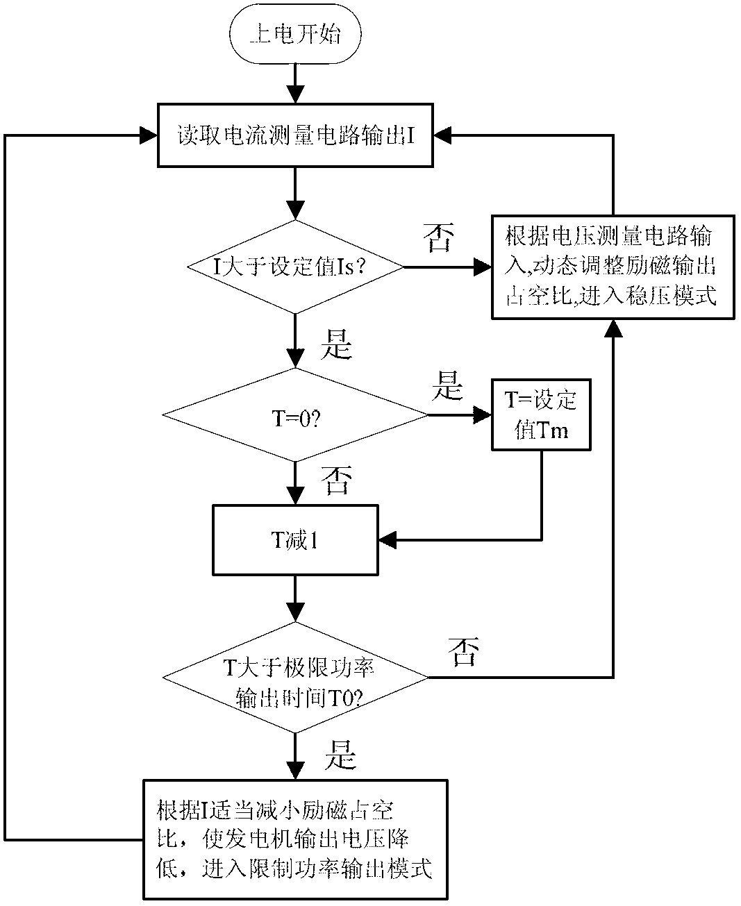
[0010] The purpose of the present invention is to overcome the defects of the prior art, and to provide a method of automatically adjusting the excitation output based on the load voltage, load current, and load duration to control the generator set in the case of inductive load startup failure due to excessive inrush current at the moment of startup. Control method of output power

Method used


Image

  • Generator excitation control system
  • Generator excitation control system

Examples


Embodiment 1

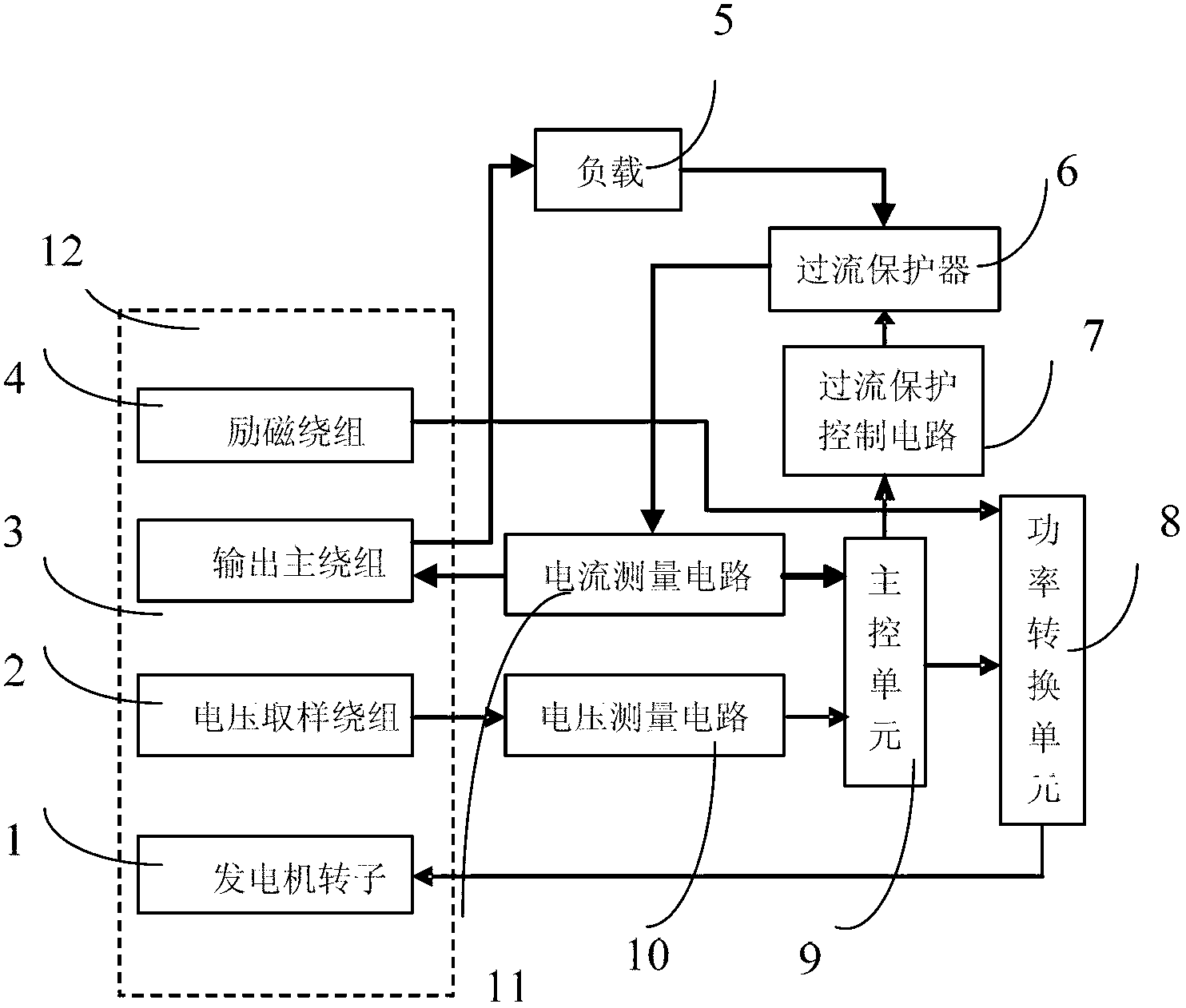
[0027] Such as figure 1 As shown, the generator excitation control system consists of generator rotor 1, voltage sampling winding 2, output main winding 3, excitation secondary winding 4, load 5, overcurrent protector 6, overcurrent protector short circuit control circuit 7, and power conversion circuit 8. The main control unit 9, the voltage measurement circuit 10 and the current measurement circuit 11 are composed of the generator 12 in the dashed frame.

[0028] The current measurement circuit 11 measures the output current of the generator output main winding 3 and outputs the measured result to the main control unit 9; the main control unit circuit 9 controls the power conversion circuit 8 according to the output of the voltage measurement circuit 10 and the current measurement circuit 11 The output duty cycle.

[0029] The overcurrent protection control circuit 7 is used to short-circuit the overcurrent protector 6 when the output of the current measurement circuit 11 is hig...

Embodiment 2

[0042] This embodiment is basically the same as the previous example, except that the control logic of the main control unit 9 is implemented by an analog circuit.


PUM


Abstract

The invention relates to a generator excitation control system. The generator excitation control system comprises a voltage measuring circuit, a current measuring circuit, a power conversion circuit and a main control unit circuit, wherein the voltage measuring circuit measures the output voltage of a generator and outputs the measured result to a main control unit; and the current measuring circuit measures the output current of the generator and outputs the measured result to the main control unit. The generator excitation control system is characterized in that: the main control unit circuit is used for controlling the output duty ratio of the power conversion circuit according to the output of the voltage measuring circuit and the current measuring circuit. The generator excitation control system can circularly realize instant large current impact output of the generator by utilizing the system inertia of a generator set. Compared with the traditional generator set with the same capacity, the generator excitation control system is more suitable for inductive impact load of high-power air conditioners, water pumps and the like.

Description

Technical field [0001] The invention relates to an excitation control system for a generator, in particular to an excitation control system for a medium and small alternating current generator set driven by a gasoline or diesel engine. Background technique [0002] Among the existing general small and medium-sized gasoline and diesel AC generator sets, generator sets with excitation control devices (commonly known as automatic voltage regulators) are favored by users because of their stable output voltage and low harmonic content. [0003] At present, the common automatic voltage regulators on the market mostly adopt the control method of output voltage closed-loop adjustment, that is, the rotor excitation duty cycle is controlled according to the generator output AC voltage: when the output voltage is high, the rotor excitation duty cycle is reduced; when the output voltage If it is too low, increase the duty cycle of the rotor excitation. This control method has good adaptab...

Claims


Application Information

Patent Timeline
Patent Type & Authority Applications(China)
IPC IPC(8): H02P9/08H02P9/10
Inventor 王运良王韶华陈伯和韦昌金
Owner SUMEC MACHINERY & ELECTRIC
Learn More