Engine power generation device

A technology for power generation devices and engines, which is used in the control of generators, electrical controls, electrical components, etc.

Inactive Publication Date: 2005-10-26
HONDA MOTOR CO LTD
View PDF3 Cites 0 Cited by
  • Summary
  • Abstract
  • Description
  • Claims
  • Application Information

AI Technical Summary

Problems solved by technology

In this way, insufficient output due to individual differences in engine output and excess output du...

Method used


Image

  • Engine power generation device
  • Engine power generation device
  • Engine power generation device

Examples


Embodiment Construction

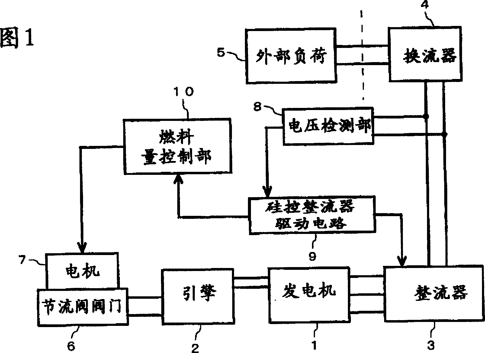
[0022] An embodiment of the present invention will be described in detail below with reference to the accompanying drawings. FIG. 1 is a block diagram showing the structure of an engine generator. A (internal combustion) engine 2 is connected to a magnetic multi-pole generator (hereinafter simply referred to as "generator") 1 with field flux provided by permanent magnets, which generator 1 is driven by the engine 2 to generate multi-phase (typically 3-phase )comminicate. This alternating current is converted into direct current by full-wave rectification through a rectifier 3 , which is composed of a rectifier circuit bridge-connected with a silicon controlled rectifier as a semiconductor rectifier element, and input to an inverter 4 . The inverter 4 supplies single-phase AC at a commercial frequency (for example, 50 Hz) to an external load 5 connected to its output side. In order to adjust the opening degree of the throttle valve of the engine 2, a stepper motor 7 is provid...


PUM


Abstract

A generator system arranged to respond to a variation in the load with a generous margin regardless of a change in the output of the generator or the engine due to degradation with the passage of time. The output current of the generator is rectified by a converter composed of thyristors in a bridge configuration of which the direct current output is converted by an inverter into an alternating current at a commercial frequency and connected to a load. The engine speed is controlled so that the conduction angle of the thyristors in the converter can be held at a target degree. As the target degree stays within a range smaller than the maximum limit, the generator runs with a margin, thus readily responding to a variation in the load. When the throttle opening is excessively opened, the target conduction angle is decreased to increase a target speed of the engine, hence inhibiting the engine from being overloaded and running at an excessive higher speed.

Description

technical field [0001] The present invention relates to an engine generator, and more particularly, to an engine generator capable of maintaining smooth control even when the engine does not generate a predetermined output by controlling the number of rotations of the engine to a target number of rotations in accordance with the magnitude of the load. Background technique [0002] An inverter device for stabilizing an output frequency is frequently used in an engine generator used as an AC power supply device. In such an engine generator, an engine connected to a generator is driven to generate an alternating current, and after converting the alternating current to a direct current, the inverter device converts the alternating current to a commercial frequency and outputs it. In a generator using an inverter device, since the output frequency does not depend on the number of revolutions of the engine, the output can be controlled according to the load by controlling the numb...

Claims


Application Information

Patent Timeline
IPC IPC(8): F02D41/02H02P9/04
CPCH02P9/04F02D2011/102F02D2041/2075F02D41/0205
Inventor 清水元寿中村政史
Owner HONDA MOTOR CO LTD
Why Eureka
Try Eureka