A laser energy control device and method

A technology of laser energy and control device, applied in the field of lithography, can solve problems such as short circuit of circuit board, laser beam cannot reach users, economic loss, etc., and achieve the effect of improving accuracy and reliability

Active Publication Date: 2019-02-05
TIANJIN JINXIN MICROELECTRONICS TECH CO LTD
View PDF6 Cites 0 Cited by
  • Summary
  • Abstract
  • Description
  • Claims
  • Application Information

AI Technical Summary

Problems solved by technology

However, the laser will generally experience energy attenuation after being used for a certain period of time, and its own control feedback signal cannot compensate for the energy attenuation of the laser, resulting in the energy of the laser beam output by the laser not reaching the energy required by the user.
When the energy of the laser beam output by the laser decays to a critical value, it will affect the subsequent exposure and development of the LDI equipment, resulting in short circuits and open circuits on the produced circuit boards.
Therefore, a laser energy control method is needed to ensure that the energy output by the laser is the energy required by the user, so as to avoid affecting subsequent exposure and development and causing economic losses

Method used


Image

  • A laser energy control device and method
  • A laser energy control device and method

Examples


no. 1 example

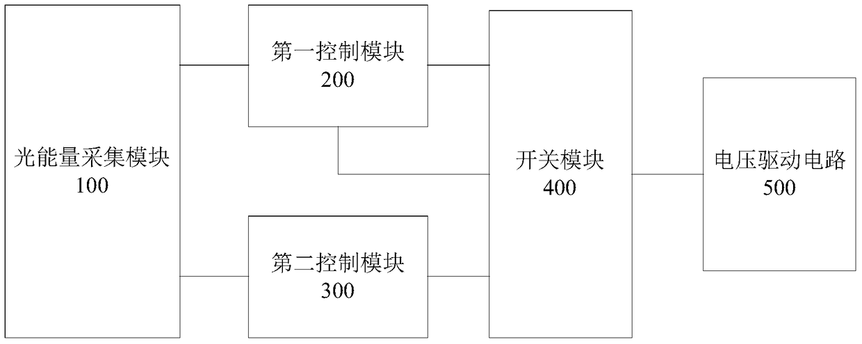
[0040] An embodiment of the present invention provides a laser energy control device, which is applied to a laser imaging system, and the device includes a light energy collection module 100, a first control module 200 and a second control module 300, such as figure 1 shown. The optical energy collection module 100 is coupled to the first control module 200 and the second control module 300 respectively, and both the first control module 200 and the second control module 300 are connected to the voltage driving circuit 500 output coupling.

[0041] Wherein, the optical energy collection module 100 is used to collect the optical energy signal of the laser beam output by the laser, and send the optical energy signal to the first control module 200 and the second control module 300 . The first control module 200 is used to compare the received light energy signal with the preset output voltage of the voltage drive circuit 500 to obtain a first difference, and feed back the first...

no. 2 example

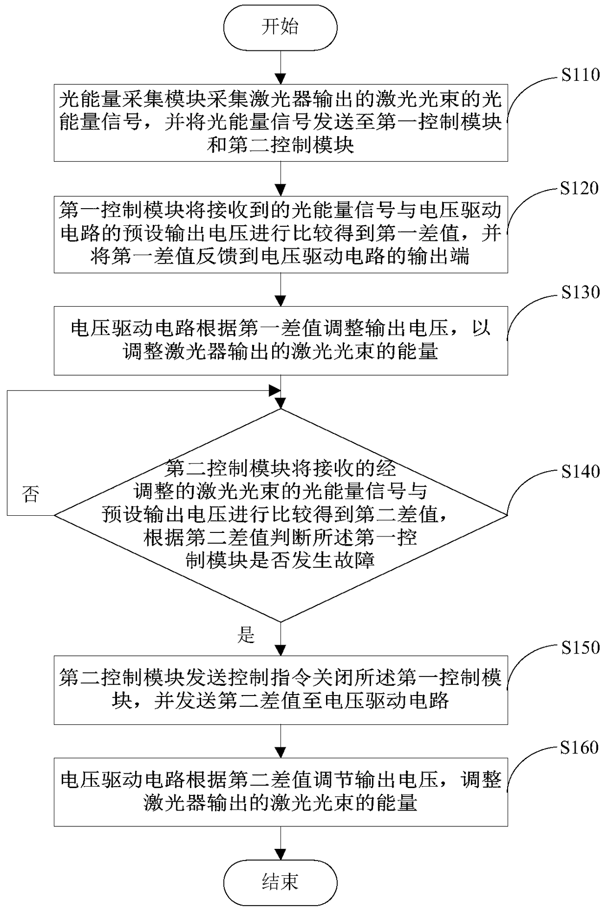
[0053] Such as figure 2 As shown, the embodiment of the present invention provides a laser energy control method, which is applied to a laser imaging system provided with a laser energy control device, and the laser energy control device includes an optical energy collection module, a first control module and a second control module ; the method comprising:

[0054] S110: The optical energy collection module collects an optical energy signal of the laser beam output by the laser, and sends the optical energy signal to the first control module and the second control module;

[0055]S120: The first control module compares the received light energy signal with the preset output voltage of the voltage drive circuit to obtain a first difference, and feeds back the first difference to the voltage drive the output of the circuit;

[0056] S130: The voltage driving circuit adjusts the output voltage according to the first difference, so as to adjust the energy of the laser beam out...


PUM


Abstract

The invention provides a laser energy control device and method, which are applied in a laser imaging system and belongs to the technical field of photoetching. The device comprises a laser energy collection module, a first control module and a second control module, wherein the laser energy collection module is coupled with each of the first control module and the second control module; the first control module and the second control module are coupled with the output end of a voltage driving circuit. According to the laser energy control device and method provided by the invention, output voltage of a driving voltage module of a laser device can be effectively controlled by the matching of the first control module and the second control module, so that the accuracy and the reliability of energy of a laser beam output by the laser device can be effectively improved.

Description

technical field [0001] The present invention relates to the technical field of photolithography, in particular to a laser energy control device and method. Background technique [0002] In the semiconductor industry and the printed circuit board industry, traditional exposure machines or Laser Dynamic Imaging (LDI) equipment are generally used in the exposure process. Unlike traditional exposure machines, LDI equipment uses laser scanning to directly print images on the printed circuit board image on the printed circuit board. Due to the finer imaging process, the control of the output energy of the laser in the LDI device is also more detailed and precise. The existing control method is to ensure the stability of the laser output energy itself through circuit adjustment. However, after a certain period of use, the laser generally experiences energy attenuation, and its own control feedback signal cannot compensate for the energy attenuation of the laser, resulting in the ...

Claims


Application Information

Patent Timeline
Patent Type & Authority Patents(China)
IPC IPC(8): H01S3/09
CPCH01S3/0959
Inventor 杨振玲刘涛张昌清
Owner TIANJIN JINXIN MICROELECTRONICS TECH CO LTD
Why Eureka
Try Eureka