Device for producing wire rope

A technology for cables and equipment, applied in the field of cable manufacturing devices, can solve problems such as filler distortion, and achieve the effect of increasing the speed of cable manufacturing

Active Publication Date: 2012-10-03
TOKYO ROPE MFG
View PDF4 Cites 9 Cited by
  • Summary
  • Abstract
  • Description
  • Claims
  • Application Information

AI Technical Summary

Problems solved by technology

Because the drum layer cannot independently twist the filler, it is not possible to have one side of the fille

Method used


Image

  • Device for producing wire rope
  • Device for producing wire rope
  • Device for producing wire rope

Examples


Embodiment Construction

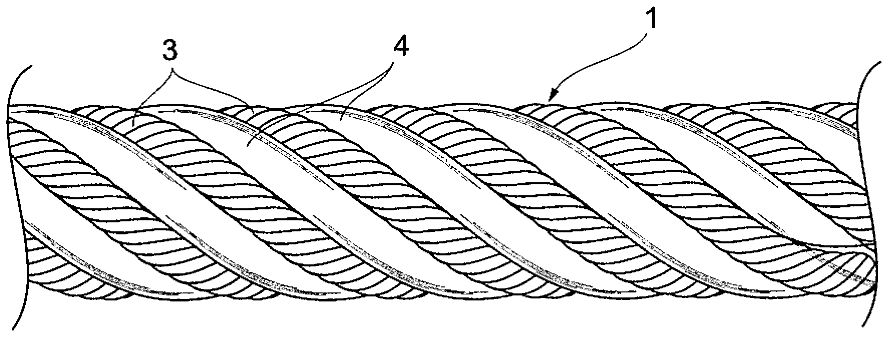
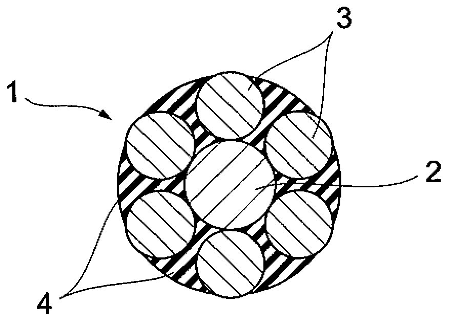
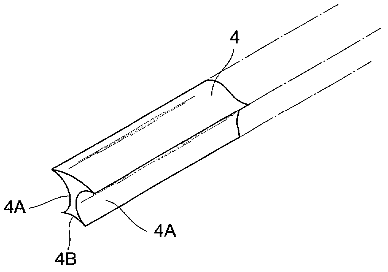
[0021] Figure 1A is the front view of cable 1, Figure 1B is a cross-sectional view of cable 1, and Figure 1C is a partially enlarged perspective view of the filler 4 contained in the cable 1 . exist Figure 1B In the sectional view of , a plurality of steel wires (wire elements) constituting each side strand 3 are not shown.

[0022] The cable 1 comprises a centrally arranged cable core 2 and is formed by laying six side strands 3 around the cable core 2, wherein each strand has a plurality of flat steel wires and the six side strands 3 lay six fillers 4 between them. The packing 4 is formed in a straight shape from a flexible material such as rubber or synthetic resin. see Figure 1B with 1C , each filler 4 has in its cross section a relatively deep recessed portion 4A formed on each side and a relatively shallow recessed portion 4B formed on the bottom. The upper side (convex part) of each filler 4 is exposed to the outside of the cable 1 . The side strands 3 are ...


PUM


Abstract

The disclosed device for producing wire rope produces a filler-filled wire rope comparatively quickly. A tubular wire twisting machine (10) and a cage wire twisting machine (20) are disposed in tandem. The rotating shaft (14) of the tubular wire twisting machine (10) and the rotating shaft (21) of the cage wire twisting machine (20) are linked. Six lateral strands (3) are wound by the feed bobbin (12) of the tubular wire twisting machine (10), and six strands of filler material (4) are wound by the feed bobbin (27) of the cage wire twisting machine (20). The six lateral strands (3) and the six strands of filler material (4) are alternately twisted around the periphery of a core rope (2) supplied from the outside, producing a filler-filled wire rope (1).

Description

technical field [0001] The present invention relates to a cable manufacturing device, and in particular to an apparatus for manufacturing a cable having resin filaments (resin filler or resin spacer) arranged between a plurality of steel side strands. Background technique [0002] Cables, especially cables for elevators, cranes etc. are generally formed by laying a plurality of side strands around a cable core. [0003] In a cable having a plurality of side strands laid around a cable core, adjacent side strands are in contact with each other. A cable has been proposed in which fillers (resin filaments), generally formed of a flexible material, are arranged between the side strands in order to prevent the side strands from rubbing against each other and thus wearing out during use (see for example Japan Patent Publication No. 57-121684). [0004] In Japanese Patent Laid-Open Publication No. 57-121684, a planetary type cable laying machine is used for making cables. In the...

Claims


Application Information

Patent Timeline
IPC IPC(8): D07B3/02D07B1/06D07B1/16
CPCD07B2207/209D07B3/06D07B3/045D07B1/167
Inventor 河原纯吉野功
Owner TOKYO ROPE MFG
Why Eureka
Try Eureka