SNCR (selective non-catalytic reduction) and SCR (selective catalytic reduction) combined process flue gas denitrification system of CFB (circulating fluidized bed) boiler

A hybrid method and denitrification technology, applied in separation methods, chemical instruments and methods, and dispersed particle separation, etc., can solve problems such as high dust and low temperature at the outlet of economizers, and achieve reduced operating costs, good economy and environmental protection performance , reduce the effect of investment

Active Publication Date: 2012-10-10
DONGFANG BOILER GROUP OF DONGFANG ELECTRIC CORP
View PDF4 Cites 20 Cited by
  • Summary
  • Abstract
  • Description
  • Claims
  • Application Information

AI Technical Summary

Problems solved by technology

For conventional power plant boilers, the flue gas temperature at the outlet of the economizer is the temperature window required for the SCR denitrification reaction, and it is arranged with high dust, the denitrification efficiency is moderate, and the technology application is mature. However, for circulating fluidized bed (CFB) boilers, the main It is characterized by high dust and low temperature at the outlet of the economizer. For some fuels with high nitrogen content and high volatile content, the NOx content at the CFB boiler outlet reaches or exceeds 400mg / Nm3 (6%O 2 , dry basis), the existing SCR (Selective Catalytic Reduction) technology can no longer meet the requirements

Method used


Image

  • SNCR (selective non-catalytic reduction) and SCR (selective catalytic reduction) combined process flue gas denitrification system of CFB (circulating fluidized bed) boiler

Examples


Embodiment Construction

[0018] The following non-limiting examples illustrate the invention.

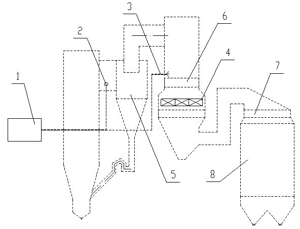
[0019] Such as figure 1 As shown, the reducing agent prepared by the reducing agent preparation system 1 is sprayed through the SNCR reducing agent injection device 3 at the inlet of the CFB boiler cyclone separator 5, and the NOx in the high-temperature flue gas at the outlet of the CFB boiler furnace is in the cyclone separator The 5 positions are strongly mixed, and part of the NOx in the flue gas undergoes a reduction reaction with the reducing agent to generate harmless and pollution-free N2 and water, which can achieve a denitrification efficiency of 50%. The incompletely reacted NOx and escaping ammonia enter the heating surface at the tail of the boiler, and then further undergo a catalytic reduction reaction through the denitrification reactor 4 arranged between the primary economizer 7 and the secondary economizer 8, and the NOx in the flue gas It is further reduced, and the denitrification effic...


PUM


Abstract

The invention discloses an SNCR (selective non-catalytic reduction) and SCR (selective catalytic reduction) combined process flue gas denitrification system of a CFB (circulating fluidized bed) boiler, wherein the system belongs to a boiler denitrification device. The SNCR and SCR combined process flue gas denitrification system comprises an SNCR denitrification device which is arranged at the upstream of flue gas and an SCR denitrification device which is arranged at the downstream of flue gas. The SNCR and SCR combined process flue gas denitrification system of the CFB boiler has the advantages that the comprehensive removal rate of NOx can reach more than 85 percent, the ammonia escape is less than 3ppm, the system is suitable for the high-dust severe environment of the CFB boiler and can meet the requirement of high denitrification efficiency, and especially under the situation that the NOx content at the outlet of the boiler is high when fuel with high content of nitrogen and volatile matters is used, the economy and the environmental performance are better. At the same time, since a flexible temperature interval and reducing agent injection selection scheme is adopted, the goal of denitrification of any kind of CFB boilers can be achieved.

Description

technical field [0001] The invention belongs to a boiler denitrification device, in particular to a CFB boiler denitrification device. Background technique [0002] At present, the mainstream technologies of flue gas denitrification devices in thermal power plants are SCR (Selective Catalytic Reduction) technology and SNCR (Selective Non-Catalytic Reduction) technology. The reactor between the preheaters removes NOx from the flue gas. A denitrification catalyst is arranged in the reactor, and the denitrification reducing agent is injected into the flue through the ammonia injection system arranged in the inlet flue to fully mix with the NOx in the flue gas. For conventional power plant boilers, the flue gas temperature at the outlet of the economizer is the temperature window required for the SCR denitrification reaction, and it is arranged with high dust, the denitrification efficiency is moderate, and the technology application is mature. However, for circulating fluidized...

Claims


Application Information

Patent Timeline
Patent Type & Authority Applications(China)
IPC IPC(8): B01D53/90B01D53/79B01D53/56
Inventor 崔有贵杨志忠叶茂
Owner DONGFANG BOILER GROUP OF DONGFANG ELECTRIC CORP
Why Eureka
Try Eureka