
Rotary type steel pipe surface cleaning device

A surface cleaning and rotating technology, applied in the field of machinery, can solve the problems that affect the smooth progress of production, unsatisfactory ash removal effect, high misjudgment rate of flaw detectors, etc., to reduce auxiliary operation time, good ash removal effect, and large coverage. Effect

Inactive Publication Date: 2012-10-10
ANGANG STEEL CO LTD
View PDF7 Cites 7 Cited by
  • Summary
  • Abstract
  • Description
  • Claims
  • Application Information

AI Technical Summary

Problems solved by technology

[0002] Before the steel pipe is inspected by the pipe body flaw detector, the outer surface of the steel pipe needs to be deashed and iron scale removed, otherwise the flaw detection will have a high misjudgment rate, which will affect the smooth progress of production
At present, the dust removal on the outer surface of the steel pipe is mainly done manually with a steel brush or polished with a small electric tool. The work efficiency is low, and the steel pipe needs to be processed off-line; The principle of the fixed steel pipe outer surface cleaning device is that a ring of steel brushes is set on the brush holder, and the steel pipe passes through the steel brushes. The disadvantages are:
[0003] 1) The coverage of the steel brush is small, and the dust removal effect is not ideal
[0004] 2) The ash removal device must be replaced every time the steel pipe production specification is changed, and the brush holder must be removed to adjust the height, which is time-consuming and laborious

Method used


Image

  • Rotary type steel pipe surface cleaning device
  • Rotary type steel pipe surface cleaning device
  • Rotary type steel pipe surface cleaning device

Examples


Embodiment Construction

[0016] The specific embodiment of the present invention will be further described below in conjunction with accompanying drawing:

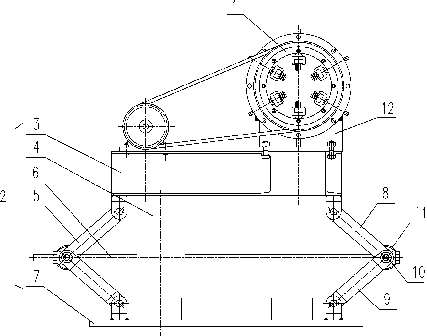
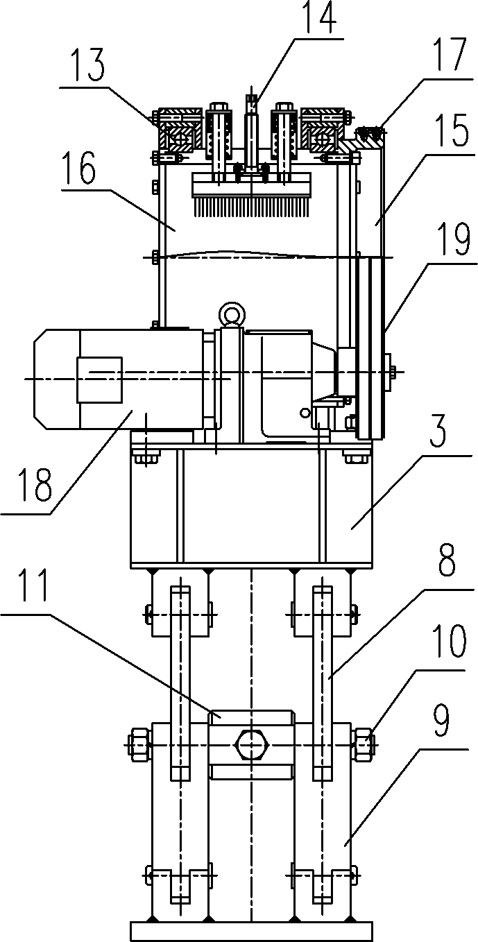
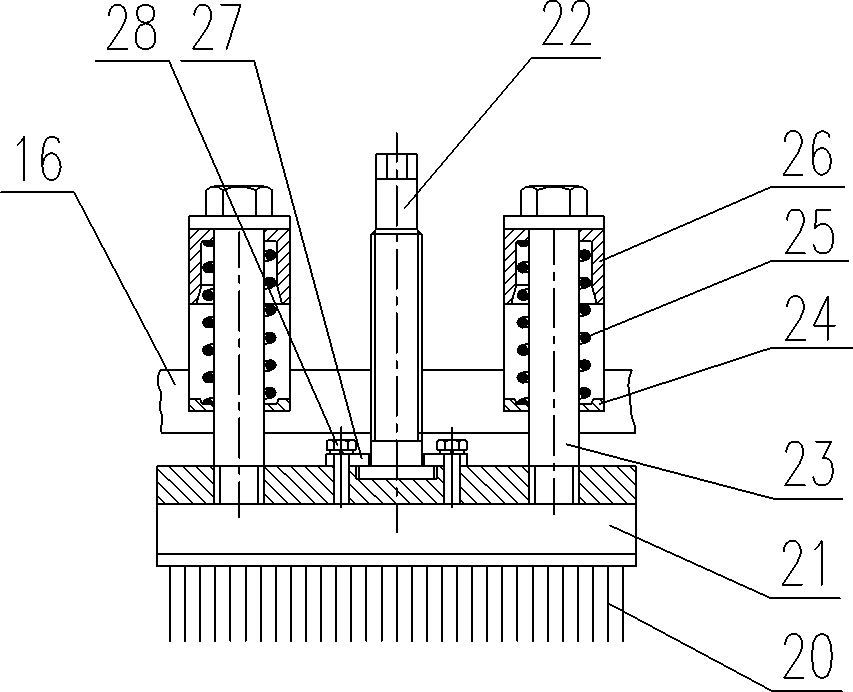
[0017] See figure 1 , figure 2 , is a structural schematic diagram of an embodiment of the rotary steel pipe surface cleaning device of the present invention. The device is arranged on the steel pipe conveying roller table and includes a rotating brush holder 1 and a lifting base 2. The rotating brush holder 1 is arranged on the lifting base 2. The lifting base 2 includes an upper platform 3, a lifting guide device 4, a lifting hinge 5, a screw adjustment mechanism 6, and a foot pad 7, and a lifting guide device 4 and a lifting hinge 5 are respectively arranged between the upper platform 3 and the foot pad 7 , the lifting hinge 5 includes an upper link 8 and a lower link 9, and a pin shaft 10 is arranged between the upper link 8 and the lower link 9, and the pin shaft 10 between the two groups of lifting hinges 5 is connected by a screw adjustme...


PUM


Abstract

The invention relates to a rotary type steel pipe surface cleaning device which is characterized by comprising a rotary brush bracket and a lifting base, wherein the rotary brush bracket is arranged on the lifting base and comprises a fixing seat, bearings, brush heads, a belt pulley and an inner ring; the bearings are arranged between the inner ring and the fixing seat; the brush heads are centripetally and circumferentially distributed on the inner ring; the belt pulley is arranged on one sides of the inner ring; the lifting base comprises an upper platform, lifting guide devices, lifting hinges, a spiral adjusting mechanism and a tail margin bearing plate; the lifting guide devices and the lifting hinges are arranged between the upper platform and the tail margin bearing plate respectively; and the two groups of lifting hinges are connected with each other through the spiral adjusting mechanism. Compared with the prior art, the invention has the benefits as follows: the covering area of steel brushes is large, the dust removing effect is good, and the accuracy of pipe body flaw detection is improved; and 2, the change of steel pipe specification is convenient and only requires corresponding adjustment but large-scale disassembly and dismounting, so as to reduce auxiliary operation time and labor intensity.

Description

technical field [0001] The invention relates to the mechanical field, in particular to a rotary steel pipe surface cleaning device. Background technique [0002] Before the steel pipe is inspected by the pipe body flaw detector, the outer surface of the steel pipe needs to be deashed and iron scale removed, otherwise the flaw detection will have a high misjudgment rate, which will affect the smooth progress of production. At present, the dust removal on the outer surface of the steel pipe is mainly done manually with a steel brush or polished with a small electric tool. The work efficiency is low, and the steel pipe needs to be processed off-line; The principle of the fixed steel pipe outer surface cleaning device is that a ring of steel brushes is set on the brush holder, and the steel pipe passes through the steel brushes. The disadvantages are: [0003] 1) The coverage of the steel brush is small, and the dust removal effect is not ideal. [0004] 2) The ash removal dev...

Claims


Application Information

Patent Timeline
IPC IPC(8): B08B9/023
Inventor 宋世岭李文奇侯永杰刘兴春韩瑛吴宇新翟立平谭峰李道刚高山
Owner ANGANG STEEL CO LTD
Learn More