
Pouring device

A technology of casting molds and driving devices, applied in ingot workshops, foundry workshops, casting equipment, etc., can solve problems such as difficult to accurately adjust the center of rotation, increased manufacturing and installation difficulties, and insufficient smooth movement, etc., to achieve small transmission power, Simple structure, improved stability and reliability

Inactive Publication Date: 2012-10-10
CHINA ENFI ENGINEERING CORPORATION
View PDF5 Cites 5 Cited by
  • Summary
  • Abstract
  • Description
  • Claims
  • Application Information

AI Technical Summary

Problems solved by technology

[0003] For the traditional large lead ingot casting machine, it is difficult to accurately adjust the center of rotation of the horizontal retaining wheel, which increases the running resistance
It is also difficult to accurately index when the peripheral pin tooth transmission is assembled, which increases the transmission power
The rotary motion of the ring is driven by peripheral pin teeth, which increases the difficulty of manufacturing and installation, and the motion is not stable enough

Method used


Image

  • Pouring device
  • Pouring device
  • Pouring device

Examples


Embodiment Construction

[0021] The embodiments of the present invention are described in detail below. Examples of the embodiments are shown in the accompanying drawings, in which the same or similar reference numerals indicate the same or similar elements or elements with the same or similar functions. The embodiments described below with reference to the drawings are exemplary, and are only used to explain the present invention, but should not be understood as limiting the present invention.

[0022] In the description of the present invention, it should be understood that the terms "center", "longitudinal", "transverse", "upper", "lower", "front", "rear", "left", "right", " The orientation or positional relationship indicated by "vertical", "horizontal", "top", "bottom", "inner", "outer", etc. are based on the orientation or positional relationship shown in the drawings, and are only for the convenience of describing the present invention and simplifying The description does not indicate or imply tha...


PUM


Abstract

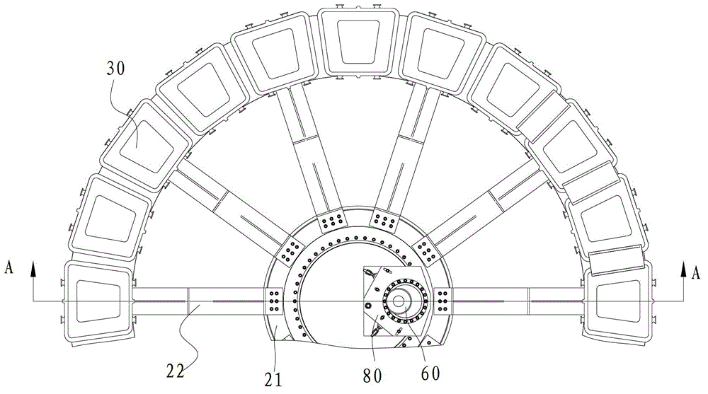
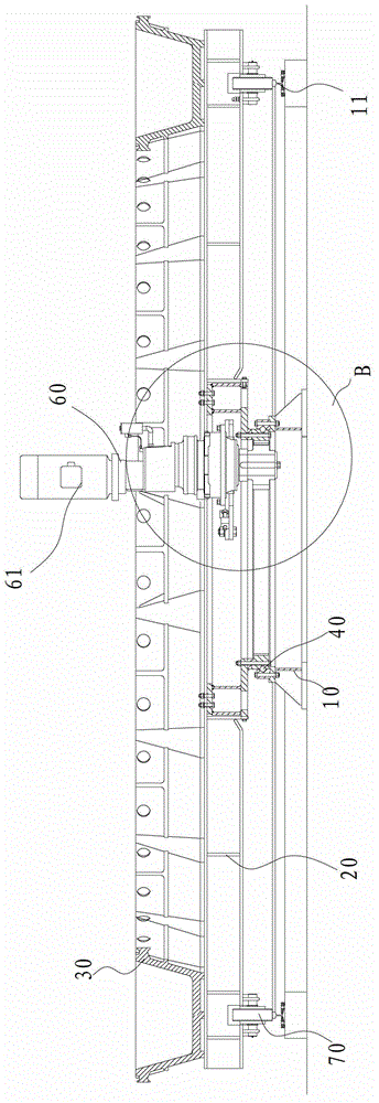
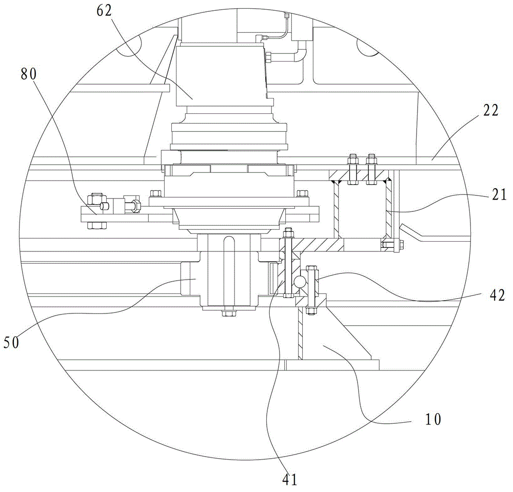
The invention discloses a pouring device. The pouring device comprises a base, a bracket, a plurality of pouring dies, a rotating bearing, a pinion and a driving device, wherein the bracket is rotatably arranged on the base; a pouring cavity of which the upper part is provided with an opening is formed on each of a plurality of pouring dies; a plurality of pouring dies are uniformly arranged on the peripheral edge of the bracket; the rotating bearing comprises an inner gear ring and an outer ring; the inner gear ring is connected with the bracket to drive the bracket to rotate; the outer ring is connected with the base; the pinion is meshed with the inner gear ring; and the driving device is arranged on the base and connected with the pinion to drive the pinion to rotate. According to the pouring device in the embodiment of the invention, the operation stability and reliability of the pouring device are improved; and the working efficiency of the pouring device is improved, transmission power is low, and the pouring device is energy-saving and environment-friendly, has a simple structure and is convenient to produce and install.

Description

Technical field [0001] The invention relates to the technical field of metallurgical equipment manufacturing, in particular to a casting device. Background technique [0002] The large lead ingot disc casting machine is a common equipment in the production of lead metallurgy, which casts molten lead into a large lead ingot of 2 tons. The large lead ingot disc casting machine places 20 lead molds along the circumference, the diameter of the disc is about 8 meters. The ring structure of the traditional large lead ingot casting machine adopts horizontal stop wheels installed on the periphery to determine the center of rotation, and the periphery of the ring structure adopts pin gear transmission. [0003] For the traditional large lead ingot casting machine, the horizontal stop wheel is difficult to accurately adjust the center of rotation, which increases the running resistance. The surrounding pin gear transmission is also difficult to accurately index when assembling, which incre...

Claims


Application Information

Patent Timeline
Patent Type & Authority Applications(China)
IPC IPC(8): B22D9/00
Inventor 刘占彬邱杰敏李洁郝朋越
Owner CHINA ENFI ENGINEERING CORPORATION
Learn More