Tool magazine and numerically-controlled machine tool using same

A technology of tool magazine and tool holder, which is applied in the direction of metal processing machinery parts, clamping, support, etc., can solve the problems of changing installation angles, CNC machine tools cannot be changed normally, etc., and achieve the effect of simple overall structure

Active Publication Date: 2012-10-10
ANHUI TATFOOK TECH CO LTD
8 Cites 23 Cited by

AI-Extracted Technical Summary

Problems solved by technology

However, because the tool magazine is set close to the operating table, the cutting fluid and debris generated during the machining of the CNC machine tool will splash on the tools cont...

Method used

The embodiment of the present invention discloses a kind of tool storehouse, comprises: knife rest; Some cutters are arranged on the knife rest respectively; The first protective cover, is relatively fixed with the knife rest; The second protective cover, with the first protective cover Rotational connection; transmission mechanism, used to control the rotation of the second protective cover relative to the first protective cover, so that the tool magazine can be switched between the open state and the closed state, wherein in the open state, the first protective cover and the second protective cover are set To allow the tool to be picked and placed from the knife holder, in the closed state, the first protective cover and the second protective cover are arranged to accommodate the tool in the accommodating space formed by the first protective cover and the second protective cover. The tool magazine of this embodiment is provided with a first protective cover and a second protective cover that have an open and closed state relative to the tool. The overall structure of the tool magazine is simple, and it can be directly installed on the side of the CNC machine tool console; It is enough to keep the tool magazine in the open state, and the closed state of the tool magazine during the machining process of the CNC machine tool can effectively protect the tool from the influence of factors such as cutting fluid/debris during the machining process.
The tool magazine 100 of the present embodiment is provided with the first protective cover 3 and the second protective cover 4 ...

Abstract

The invention discloses a tool magazine and a numerically-controlled machine tool using the same. The tool magazine comprises a tool rest, a plurality of tools, a first protective cover, a second protective cover and a transmission mechanism, wherein the tools are arranged on the tool rest; the first protective cover is fixed with the tool rest relatively; the second protective cover is connected with the first protective cover in a rotational mode; the transmission mechanism is used for controlling the second protective cover to rotate relative to the first protective cover, so that the tool magazine is switched between the opening state and the closing state; the tools can be allowed to be stored in and taken out of the tool rest by arranging the first protective cover and the second protective cover in the opening state; and the tools are accommodated in accommodating space formed by the first protective cover and the second protective cover by arranging the first protective cover and the second protective cover in the closing state. Due to the adoption of the mode, the tool magazine can protect the tools against influence of factors such as cutting fluid/fragments in the machining process effectively in the closing state.

Application Domain

Protection and storage accessoriesPositioning apparatus +2

Technology Topic

Image

  • Tool magazine and numerically-controlled machine tool using same
  • Tool magazine and numerically-controlled machine tool using same
  • Tool magazine and numerically-controlled machine tool using same

Examples

  • Experimental program(1)

Example Embodiment

[0018] The technical solutions in the embodiments of the present invention will be clearly and completely described below in conjunction with the accompanying drawings in the embodiments of the present invention. Obviously, the described embodiments are only a part of the embodiments of the present invention, rather than all the embodiments. Based on the embodiments of the present invention, all other embodiments obtained by those of ordinary skill in the art without creative work shall fall within the protection scope of the present invention.
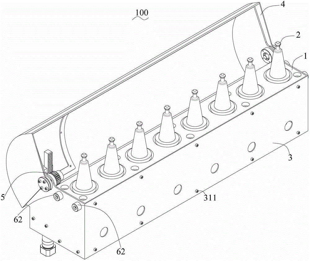
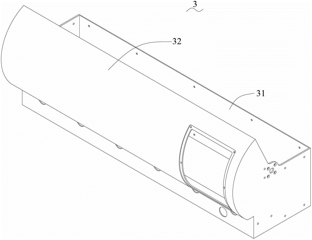
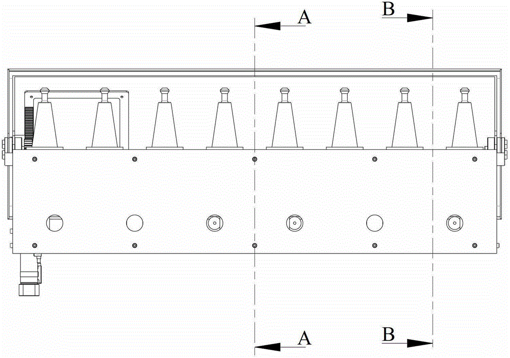
[0019] The embodiment of the present invention discloses a tool magazine, which includes: a tool holder; a plurality of knives are respectively arranged on the tool holder; a first protective cover, which is relatively fixed to the tool holder; a second protective cover, which is rotatably connected with the first protective cover; The transmission mechanism is used to control the rotation of the second protective cover relative to the first protective cover to switch the tool magazine between the open state and the closed state. In the open state, the first protective cover and the second protective cover are set to allow The tool holder takes and places the tools. In the closed state, the first protection cover and the second protection cover are arranged to accommodate the tools in the accommodation space formed by the first protection cover and the second protection cover. The tool magazine of this embodiment is provided with a first protective cover and a second protective cover that are opened and closed relative to the tool. The overall structure of the tool magazine is simple and can be directly installed on the side of the CNC machine tool operating table; It is enough to keep the tool magazine in the open state, and the closed state of the tool magazine during the machining of the CNC machine tool can effectively protect the tool from the cutting fluid/debris during the machining process.
[0020] See figure 1 The tool magazine 100 in the embodiment of the present invention includes a tool holder 1, a plurality of tools 2, a first protective cover 3, a second protective cover 4 and a transmission mechanism 5.
[0021] The tool 2 is set on the tool holder 1. In this embodiment, the tool holder 1 is provided with a plurality of containing holes (not shown) for fixing the tool 2, and the tool 2 is arranged on the tool holder 1 through the containing holes and a part of the tool holder 1 is exposed. In practical applications, the way the tool holder 2 fixes the tool 1 should not be limited by this. For example, a chuck is provided on the tool holder 2, and the tool 1 is clamped and fixed to the tool holder 2 by the chuck.
[0022] The first protective cover 3 is fixed to the tool holder 1, and the second protective cover 4 is rotatably connected to the first protective cover 3. In this embodiment, the first protective cover 3 is connected to the tool holder 1 by a screw 311. In practical applications, the fixing method between the first protective cover 3 and the tool holder 1 should not be limited by this. For example, the first protective cover 3 and the tool holder 1 are respectively provided with matching clamping mechanisms to make them relatively fixed. Or both can be relatively fixed through integrated design.
[0023] The transmission mechanism 5 is used to control the rotation of the second protective cover 4 relative to the first protective cover 3 so as to switch the tool magazine 100 between an open and a closed state. in figure 1 In the open state shown, the tool 2 is exposed from the tool magazine 100, so the first protective cover 4 and the second protective cover 3 are configured to allow the tool 2 to be taken and placed from the tool holder 1. In the closed state, the first protective cover 3 and the second protective cover 4 form an accommodating space to house the cutter 2 therein.
[0024] The tool magazine 100 of this embodiment is provided with a first protective cover 3 and a second protective cover 4 that are opened and closed relative to the tool 2. The overall structure of the tool magazine 100 is simple, and it can be directly installed on a CNC machine tool console (not shown) ); when changing tools, you only need to make the tool magazine 100 open, and the closed state of the tool magazine 100 can effectively protect the tool 2 from factors such as cutting fluid/debris during machining. Impact. At the same time, the opening and closing of the tool magazine 100 only needs to rotate the second protective cover 4 relative to the first protective cover 3, and the design is simple. The second protective cover 4 can be made of lightweight, corrosion-resistant, and structurally strong materials. , So that the energy consumption is lower when the tool magazine 100 is opened and closed.
[0025] Please refer to Figure 2-5 , The first protective cover 3 includes a square shell 31 and a first sector-shaped cylindrical shell 32 connected to each other. The tool holder 1 is housed in the square housing 31 and a part of the tool 2 is exposed from the tool holder 1 and the square housing 2. The shapes of the square housing 31 and the tool holder 1 match each other and they are fixedly connected by screws 311. In this way, the flat surface of the square housing 31 allows the tool magazine 100 to be easily connected to the CNC machine tool (not shown) using the tool magazine 100 through the square housing 31. Moreover, because the shape of the square housing 31 and the shape of the tool holder 1 match each other, the volume and cost of the tool magazine 100 can be effectively controlled.
[0026] The tool holder 1 is roughly in the shape of a rectangular parallelepiped, and includes an upper plate 11, a lower plate 13 and a spacer supported between the upper plate 11 and the lower plate 13 arranged at intervals. The upper plate 11 and the lower plate 13 are respectively provided with a plurality of accommodating holes (not shown) corresponding to each other. The tool 2 is set on the tool holder 1 through the containing holes of the upper plate 11 and the lower plate 12 and a part of the tool holder 1 is exposed.
[0027] In practical applications, the shape of the first protective cover 3 should not be limited by this. For example, the first protective cover 3 may be configured as an overall fan-shaped cylindrical shape or an overall square shape that accommodates the tool holder 1.
[0028] The second shield 4 includes a second sector-shaped cylindrical shell 41. The first sector-shaped cylindrical shell 32 and the second sector-shaped cylindrical shell 41 are rotationally connected in a coaxial manner. For details, please refer to figure 1 , Figure 4 with Figure 5. The shaft of the first sector-shaped cylindrical shell 32 is provided with a bearing 321, and the shaft of the second sector-shaped cylindrical shell 41 is provided with a rotating shaft 42. The rotating shaft 42 is connected to the bearing 321, and the shaft 42 and the bearing 321 cooperate The first protective cover 3 and the second protective cover 4 are connected in rotation.
[0029] The first sector-shaped cylindrical shell 32 and the second sector-shaped cylindrical shell 41 each include two sector-shaped side faces (not shown) and an arc surface (not shown) connecting the two sector-shaped side faces, wherein the two sector-shaped cylindrical shells The arc surfaces of the bodies match each other, and the arc surface of the second sector-shaped cylindrical shell 41 is located outside the arc surface of the first sector-shaped cylindrical shell 32. The arc surface of the sector-shaped cylindrical shell can make the cutting fluid/debris in the machining process slide off the second protective cover 4, avoiding the accumulation of cutting fluid/debris on the second protective cover 4, so that the second protective cover 4 It is difficult to open or close, resulting in the inability to replace the tool, which has a bad influence on the CNC system.
[0030] In order to be beautiful and cost-saving, the embodiment of the present invention adopts a rotating shaft 42 and a bearing 321 to cooperate at both ends of the first protective cover 3 and the second protective cover 2 respectively. In practical applications, the rotating shafts 42 mounted on the two ends of the second protective cover 4 may share a long rotating shaft.
[0031] The transmission mechanism 5 is installed to one end of the tool magazine 100. Please refer to Figure 6-Figure 8 The transmission mechanism 5 includes a gear 51 concentrically fixed to the rotating shaft 42, a rack 52 meshing with the gear 51, a power device 53, an adapter block 55 connecting the power device 53 and the rack 52, a bracket 56 and a stop bar 54. Wherein, the power unit 53 is fixed to the first protective cover 3 through a bracket 56. The stopper 54 is used to keep the rack 52 and the gear 51 in a good meshing state. The rack 52 is arranged vertically, and the power device 53 drives the rack 52 to move up/down through the adapter block 55, thereby driving the gear 51 to rotate in a clockwise/counterclockwise direction, so that the shaft 42 rotates relative to the bearing 321, thereby controlling the second The protective cover 2 rotates relative to the first protective cover 3, so that the tool magazine 100 can be switched between the open state and the closed state. In practical applications, the rack 52 can also be placed horizontally or obliquely as required. Among them, the arc surface structure of the second sector-shaped cylindrical shell 41 can make the gear 51 have a balanced force arm when rotating, and the force is uniform, the gear 51 is less worn, and the life of the product is increased.
[0032] In this embodiment, the power unit 53 is a cylinder. In practical applications, the power device 53 can be any power mechanism that can drive the rack 52 to shift. At the same time, a numerical control system is used to control the power device 53. When the tool 2 is exchanged, the power device 53 is controlled to operate to make the second protective cover 4 Open, and close the second protective cover 4 when the tool 2 is exchanged. For example, when the power unit 53 is a cylinder, the numerical control system can control the cylinder by controlling the air compressor to achieve the purpose of opening or closing the second protective cover 4, thereby realizing the full automation and numerical control of the opening and closing of the tool magazine protective cover. Synchronization of machine tools.
[0033] At the same time, the transmission mechanism 5 may also include a gear 51 concentrically fixed to the rotating shaft 42, a chain meshing with the gear 51, and a stepping motor; the stepping motor drives the chain to drive the gear 51 to achieve the purpose of opening or closing the tool magazine 100. The stepper motor can achieve higher control accuracy and can be better synchronized with the CNC system. Ordinary motors can be used for cost considerations.
[0034] Please refer to figure 1 with Figure 4 , The tool magazine 100 of the embodiment of the present invention further includes the tool magazine 100 provided on the first protective cover 3 for reducing the rotation of the second protective cover 4 relative to the first protective cover 3 to the open state of the tool magazine 100 ( Figure 4 (Shown) or closed state (not shown), the shock-absorbing mechanism 61, 62. Figure 4 Shown is a buffer mechanism 61 that reduces the buffer force when the second protective cover 4 rotates to the open state of the tool magazine 100. In practical applications, users can easily think of applying the buffer mechanism 6 to the position of the first protective cover 3 when the second protective cover 4 is rotated to the closed state of the tool magazine 100, such as figure 1 The buffer mechanism 62 shown. The specific structure of the buffer mechanism 61, 62 can be a whole piece of elastic buffer material, or a mechanism with spring elements, and so on.
[0035] Different from the existing technology. The tool magazine 100 of the embodiment of the present invention is provided with a first protective cover 3 and a second protective cover 4 that are open and closed relative to the tool 2. The overall structure of the tool magazine 100 is simple, and it can be directly installed on a CNC machine tool console (not shown) When changing tools, you only need to make the tool magazine 100 open, and the closed state of the tool magazine 100 effectively protects the tool 2 from factors such as cutting fluid/debris during machining. Impact.
[0036] The present invention also provides a numerical control machine tool using the tool magazine 100 described above.
[0037] The above are only the embodiments of the present invention, and do not limit the scope of the present invention. Any equivalent structure or equivalent process transformation made by using the content of the description and drawings of the present invention, or directly or indirectly applied to other related technologies In the same way, all fields are included in the scope of patent protection of the present invention.

PUM

no PUM

Description & Claims & Application Information

We can also present the details of the Description, Claims and Application information to help users get a comprehensive understanding of the technical details of the patent, such as background art, summary of invention, brief description of drawings, description of embodiments, and other original content. On the other hand, users can also determine the specific scope of protection of the technology through the list of claims; as well as understand the changes in the life cycle of the technology with the presentation of the patent timeline. Login to view more.

Similar technology patents

Integrated embedded pipe hot stamping die for automobile parts

InactiveCN102029310AManufacturing process cycle and cost reductionThe overall structure is simpleShaping toolsMotor vehicle partHot stamping
Owner:BAOSHAN IRON & STEEL CO LTD

Classification and recommendation of technical efficacy words

Why Eureka
Try Eureka