
Sterile material transport device

A transfer device and material technology, applied in the direction of transportation and packaging, conveyor objects, conveyors, etc., can solve the problems of inconvenient transportation and assembly, affecting the transfer speed, and many transfer actions

Active Publication Date: 2012-10-10
浙江亚光科技股份有限公司
View PDF10 Cites 5 Cited by
  • Summary
  • Abstract
  • Description
  • Claims
  • Application Information

AI Technical Summary

Problems solved by technology

Since the specific equipment connected with the box body is usually high, the track in the aseptic space of the box body needs to be consistent with the height of the connecting equipment to be able to put the sterile materials in the transfer vehicle into the connecting equipment, and The box also needs to be equipped with supporting parts for various equipment, resulting in a large footprint and volume, which is inconvenient for transportation and assembly
After continuous research and development by technicians in this field, some transfer equipment that reduces the footprint and volume of the box body has also appeared. This type of equipment is equipped with a lifting platform at the output end of the track in the internal sterile space that can lift the transfer vehicle. , when the transfer vehicle loaded with sterile materials arrives at the lifting platform, the lifting platform lifts the transfer vehicle to a space consistent with the height of the connecting equipment. Although this type of operation reduces the area of ​​the box to a certain extent , however, there are many rotations and complex mechanisms. Pneumatic actuators or electric actuators damage parts of the sterile passage, which may cause secondary pollution to the sterile environment, which is not conducive to internal cleaning and affects the transfer speed. reduce transmission efficiency

Method used


Image

  • Sterile material transport device
  • Sterile material transport device
  • Sterile material transport device

Examples


Embodiment Construction

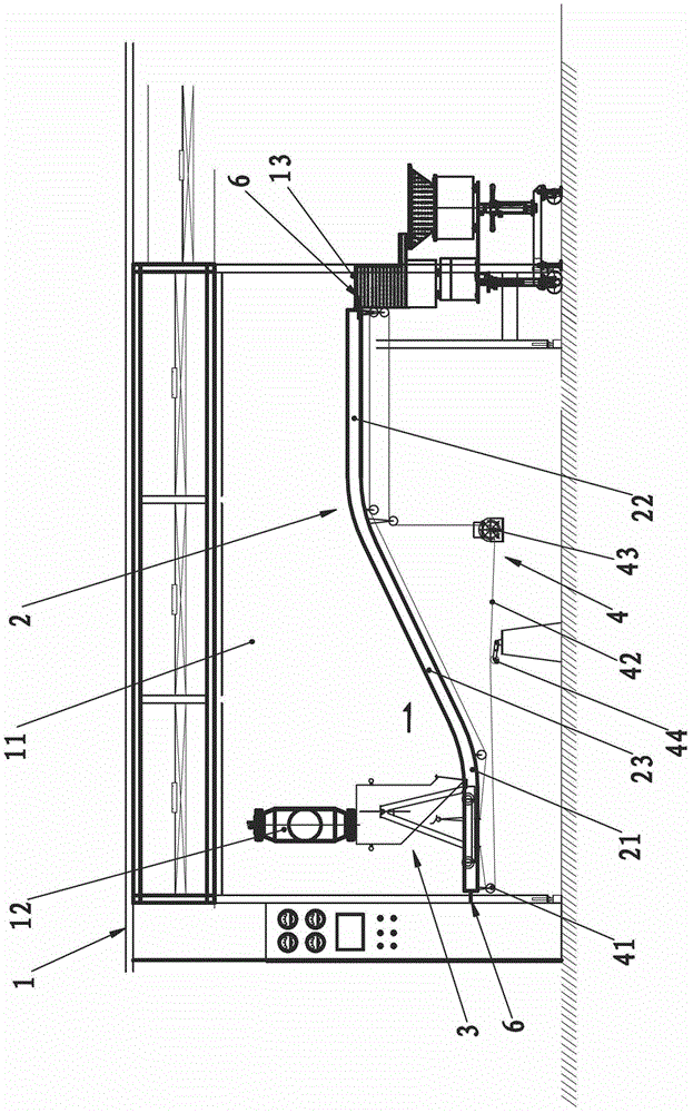
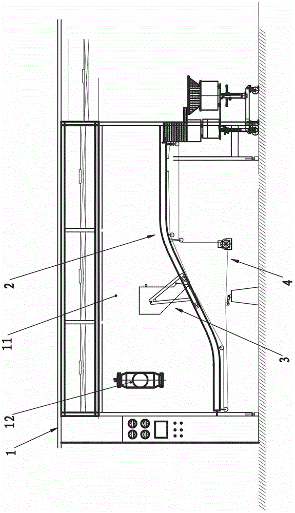
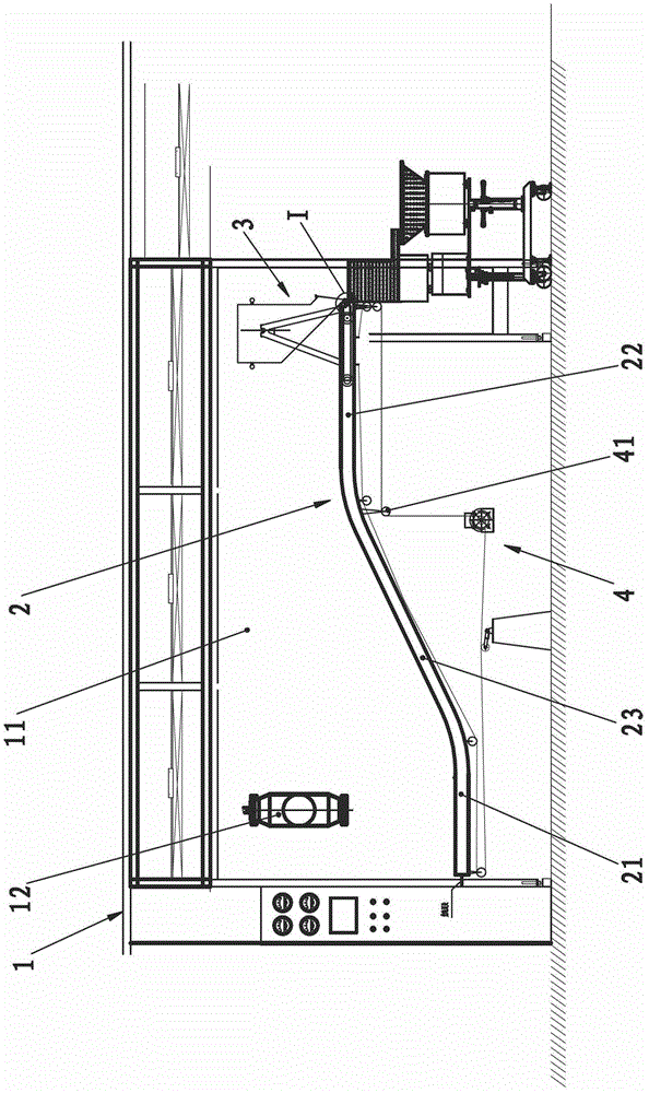
[0020] Such as figure 1 — Image 6 The aseptic material transfer device shown includes a box body 1 with a sterile space 11, a track 2 located in the sterile space 11, a transfer vehicle 3 that can run along the track 2, and a drive that drives the transfer vehicle 3 to run. Mechanism 4, one end of the track 2 in the transverse direction of the box body 1 is the input end 21, and the other end is the output end 22, the box body 1 is located at the corresponding place of the input end 21 and is provided with a material receiving port 12, and the box body 1 is located at its output end 21 is provided with a discharge port 13 connected with external equipment, the input end 21 and output end 22 of the track 2 are arranged in parallel, and the position of the output end 22 in the sterile space 11 is higher than the input end 21, the input end of the track 2 The end 21 and the output end 22 are connected by an inclined transfer end 23; the transfer vehicle 3 includes a transport f...


PUM


Abstract

The invention relates to auxiliary medical cleaning equipment, and in particular relates to a sterile material transport device. The technical scheme is as follows: the sterile material transport device comprises a box body with a sterile space, a rail arranged in the sterile space, a transport vehicle and a transport vehicle driving mechanism, wherein one end, which is positioned in the transverse direction of the box body, of the rail is provided with an input end, and the other end of the rail is provided with an output end; a corresponding part, positioned at the input end, of the box body is provided with a collecting port; the output end of the box body is provided with a discharging hole; the input end and output end of the rail are arranged in parallel; the part, positioned in the sterile space, of the output end is higher than that of the input end; the input end and output end of the rail are connected through an oblique transfer end; the transport vehicle comprises a conveying frame and a carrying barrel hinged with the conveying frame through a hinge; and the center of gravity of the carrying barrel and a central line of the hinged shaft which longitudinally penetrates through the axis are always positioned on the same plane. By utilizing the technical scheme, the sterile material transport device has the advantages of occupying small area, shortening the transmission time and improving the transmission efficiency.

Description

technical field [0001] The invention relates to a medical cleaning auxiliary equipment, in particular to a sterile material transfer device. Background technique [0002] Pharmaceutical processing equipment has strict requirements on the disinfection and aseptic treatment of its processed products. However, because there are many types of medical equipment, such as equipment for cleaning medical rubber stoppers, it needs to go through multiple disinfection procedures before it can be put into use. During the disinfection process, it needs to be processed by different equipment. The transfer between the two kinds of equipment requires independent transfer equipment. At present, the aseptic transfer equipment that appears on the market and materials is mainly composed of a box with a sterile space, a straight track in the sterile space, and a transfer vehicle running along the track. Since the specific equipment connected with the box body is usually high, the track in the ...

Claims


Application Information

Patent Timeline
IPC IPC(8): B65G35/00B65G47/34
Inventor 李建设
Owner 浙江亚光科技股份有限公司
Learn More