Forming method of upward pull type overhanging joist steel moudle frame stressing platform

A force-bearing platform and forming method technology, which is applied in the fields of formwork/template/work frame, on-site preparation of building components, construction, etc. The mechanical force state is prone to change, the force platform is deformed, etc., to achieve scientific and reliable structural force, good social and economic benefits, and structural force balance and reasonable effects.

Inactive Publication Date: 2012-10-10
HENAN NO 1 CONSTR ENG GRP
View PDF5 Cites 9 Cited by
  • Summary
  • Abstract
  • Description
  • Claims
  • Application Information

AI Technical Summary

Problems solved by technology

The traditional cantilevered formwork platform is not properly set up at the connection node between the I-beam and the round steel and the connection node between the round steel and the embedded part. The connection between the components is generally welded. In the I-beam cantilever formwork When the platform is under stress, the stress platform formed by welding is prone to deformation, the weld may be torn, and the overall mechanical stress state is easy to change, which greatly threatens the safety of construction.
[0003] At present, the country has not formulated corresponding specifications for the force platform of the cantilevered formwork that bears the load of concrete structures such as overhanging eaves, and there is no standardized forming method for the force platform of the I-steel cantilevered formwork

Method used


Image

  • Forming method of upward pull type overhanging joist steel moudle frame stressing platform
  • Forming method of upward pull type overhanging joist steel moudle frame stressing platform
  • Forming method of upward pull type overhanging joist steel moudle frame stressing platform

Examples


Embodiment 1

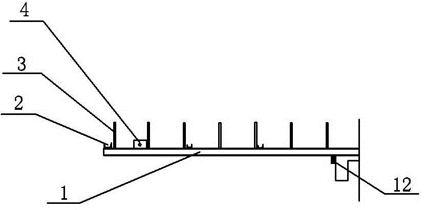
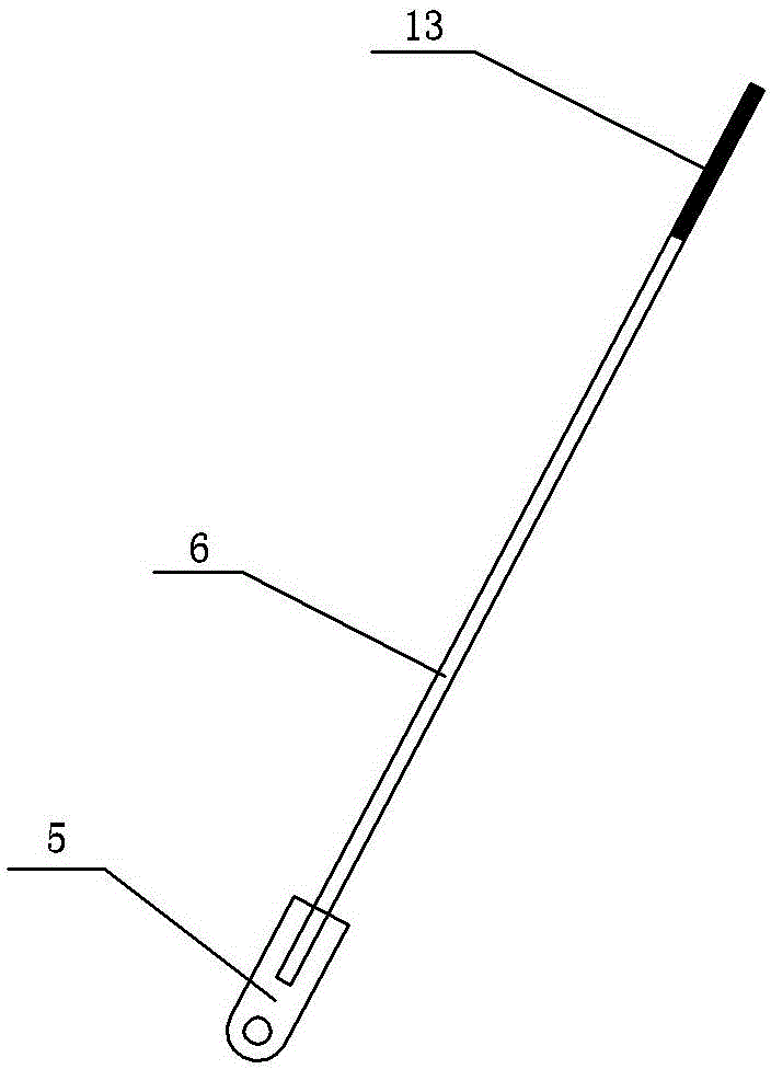
[0031] Embodiment 1 A forming method of a pull-up cantilevered I-beam formwork bearing platform includes the following steps:

[0032] (1) Cantilevered I-beams are fabricated (see figure 2 ): The cantilevered I-beam adopts 18# or 20# I-beam, and the length of the I-beam is 9m, of which the length of the cantilever is 6m. The lower ear plate 4 is welded 1m away from the end of the I-beam. The lower ear plate 4 is made of a steel plate with a specification of 200×300×20mm and a weld length of 200mm. There is a circular hole with a diameter of 30mm at the center of the lower lug plate 4, which is used to realize the anchor bolt connection between the lower lug plate 4 and the lower connecting plate 5 of the cable-stayed round steel 6. A 50×100×10mm steel plate is welded at the junction of the I-beam and the structural floor edge beam, and the weld length is 100mm. Since the end of the cantilevered I-beam 1 welds a φ25 socket steel bar head 3 in the center of its upper surface ...


PUM


Abstract

The invention relates to a forming method of an upward pull type overhanging joist steel moudle frame stressing platform. The forming method comprises the following steps: enabling an overhanging joist steel to weld a connecting plate pull knot on a pre-burying otic placode of a floor structure through an inclined pull round steel, and realizing a pull connection main stress; adopting two bolted connections on a joist steel direction which is perpendicular to the upper surface of the middle of the overhanging joist steel, enabling a channel steel to be as a pull knot rod piece, adopting one bolted connection on the joist steel direction which is perpendicular to the upper surface of the end part of the overhanging joist steel, utilizing the channel steel to strengthen the end part of the overhanging joist steel, and connecting each overhanging joist steel and the channel steel so as to form a whole well-shaped combination stress platform; and welding a vertical rod bearing insertion steel bar head on the overhanging joist steel based on the vertical rod position supported by a moudle frame, welding a steel baffle plate on the edge beam position of the overhanging joist steel and the floor structure, wherein the steel baffle plate is used for generating horizontal thrust after balanced construction stress. The forming method provided by the invention simplifies the construction procedures, reduces construction difficulty, and simultaneously ensures construction safety; and the stress of the stress platform overall structure is reasonable, and the stress platform overall structure is safe and reliable.

Description

technical field [0001] The invention relates to the technical field of building construction, in particular to a method for forming a force-bearing platform of a pull-up cantilevered I-beam formwork for a building. Background technique [0002] With the development of my country's economic construction, there are more and more high-rise buildings in cities. Concrete roof overhangs are often used in the design of modern high-rise buildings. The horizontal distance from the overhangs to the facade of high-rise buildings can generally reach 4-6m. Although this design of concrete overhangs achieves a beautiful and generous appearance visual effect, Also caused bigger construction difficulty to building construction link. Since the position of the overhanging eaves of the concrete roof is relatively high, and the overhanging part of the construction will generate a large construction load, in order to ensure structural safety and save formwork costs during construction, a cant...

Claims


Application Information

Patent Timeline
Patent Type & Authority Applications(China)
IPC IPC(8): E04G13/06
Inventor 张文锋苏富金赵海勇冀小辉史瑞李坤李广辉郭兵兵蒋全成刘鹏宇徐勇蔡超
Owner HENAN NO 1 CONSTR ENG GRP
Why Eureka
Try Eureka