Metal vacuum high-temperature heat collection pipe

A heat collector tube and metal inner tube technology, applied in the field of solar energy applications, can solve the problem of inability to obtain high temperature, and achieve the effects of improving heat collection efficiency, reducing the number of use, and reducing floor space.

Inactive Publication Date: 2012-10-10
朱雷
View PDF4 Cites 1 Cited by
  • Summary
  • Abstract
  • Description
  • Claims
  • Application Information

AI Technical Summary

Problems solved by technology

[0004] The object of the present invention is to propose a metal vacuum high-temperature heat collecting tube, which can keep the heat collecting tube at The thermal radiation emitted at high temperature is reflected back to the heat collecting tube and absorbed, which effectively increases the heat collecting temperature of the heat collecting tube

Method used


Image

  • Metal vacuum high-temperature heat collection pipe
  • Metal vacuum high-temperature heat collection pipe
  • Metal vacuum high-temperature heat collection pipe

Examples


Embodiment Construction

[0021] The present invention will be further described below in conjunction with the drawings.

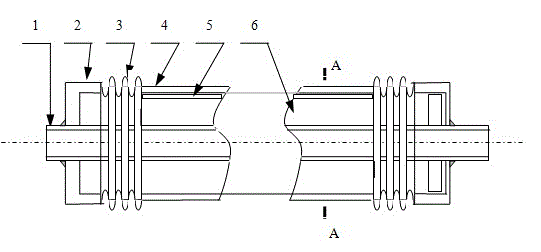
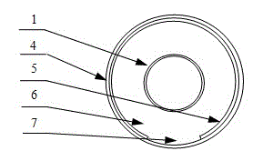
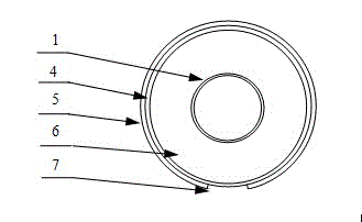
[0022] by figure 1 It can be seen that the metal vacuum high-temperature heat collection tube includes a glass outer tube 4, a metal inner tube 1, a corrugated tube 3, and a connecting flange 2 penetrating through the glass outer tube 4. The outer wall of the metal inner tube 1 is coated with an anti-reflection layer, and the glass outer tube 4 A bellows 3 is hermetically connected at both ends, and the other end of the bellows 3 is hermetically connected to the metal inner tube 1 through a connecting flange 2, and a vacuum chamber 6 is formed between the glass outer tube 4, the corrugated tube 3 and the metal inner tube 1. The glass outer tube 4 is covered with a heat-insulating reflective layer 5; the heat-insulating reflective layer 5 has an incident window 7, which is parallel to the central axis of the glass outer tube 4 and extends from one end of the glass outer tube 4 to At th...


PUM


Abstract

The invention relates to a metal vacuum high-temperature heat collection pipe, which includes a glass outer pipe, a metal inner pipe penetrating the glass outer pipe, corrugated pipes and connecting flanges, wherein the two ends of the glass outer pipe are hermetically connected with the corrugated pipes respectively; the corrugated pipes are hermetically connected onto the metal inner pipe through the connecting flanges; and a vacuum cavity is formed between the glass outer pipe, the corrugated pipes and the metal inner pipe. The metal vacuum high-temperature heat collection pipe is characterized in that the glass outer pipe is wrapped with a thermal insulation reflective layer provided with an entrance window; the entrance window is parallel to the medial axis of the glass outer pipe, and extends to the other end from one end of the glass outer pipe; and the width of the entrance window is 20 to 180 radian. As the glass outer pipe of the heat collection pipe is wrapped with a thermal insulation reflective layer, the thermal radiation emitted by the heat collection pipe at a high temperature is reflected back to the heat collection pipe for secondary absorption, and further effectively increase the heat collection temperature of the heat collection pipe, as a result, the use amount of heat collection pipes designed for object thermal energy heat collection is reduced, the investment scale for the heat collection system is reduced, and the occupied area is reduced.

Description

Technical field [0001] The invention relates to the field of solar energy applications, in particular to a metal vacuum high-temperature heat collecting tube in a solar heat utilization system. Background technique [0002] The heat loss is explained in mechanism as three ways of gas convection, material conduction and radiation. The collector tube is a key component of a solar collector. Generally, there are composite glass collector tubes, metal collector tubes, and metal vacuum collector tubes composed of glass and metal tubes. Among the metal vacuum heat collection tubes reported so far, they are generally composed of a glass outer tube, a flange, a corrugated tube, and a metal inner tube. The metal inner tube runs through the glass outer tube. During processing, the end of the glass outer tube, flanges, bellows, and the outer wall of the metal inner tube are welded and sealed in sequence to form a vacuum cavity in the glass outer tube, and solar energy reaches the vacuum ca...

Claims


Application Information

Patent Timeline
Patent Type & Authority Applications(China)
IPC IPC(8): F24J2/46
CPCY02E10/40
Inventor 朱雷
Owner 朱雷
Why Eureka
Try Eureka