Compound parabolic concentrating power generation-phase change heat storage device

A compound paraboloid, phase change heat storage technology, applied in photovoltaic power generation, photovoltaic thermoelectric hybrid power generation, solar thermal power generation, etc. The overall efficiency, the heat transport loss is small, the effect of avoiding heat energy waste

Active Publication Date: 2020-01-14
BEIJING UNIV OF TECH
View PDF8 Cites 1 Cited by
  • Summary
  • Abstract
  • Description
  • Claims
  • Application Information

AI Technical Summary

Problems solved by technology

[0003] On the other hand, although the advantages of thermoelectric materials are obvious, the power generation efficiency of thermoelectric materials is relatively low at present. In order to increase their power generation power, traditional thermoelectric power generation devices often choose concentrators with high concentration ratios to provide higher energy for thermoelectric power generation sheets. Density of solar radiation, thereby increasing the temperature of the hot end of the power generation material
This method will inevitably make the body of the power generation device bulky, and due to the high temperature of the power generation sheet, the heat loss of the power generation device will be serious, and the waste heat generated during the power generation process cannot be recovered and is directly wasted.
[0004] In addition, traditional thermal power generation devices can only provide heat energy for thermal power generation materials when the sun exists, so that the application of power generation devices is limited by the characteristics of solar energy itself

Method used


Image

  • Compound parabolic concentrating power generation-phase change heat storage device
  • Compound parabolic concentrating power generation-phase change heat storage device
  • Compound parabolic concentrating power generation-phase change heat storage device

Examples


Embodiment 1

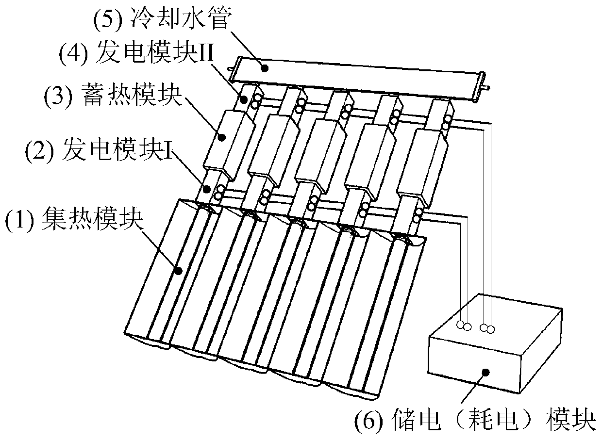
[0034] figure 1It is a schematic diagram of the three-dimensional structure of the present invention. The present invention is divided into 6 main function modules, namely heat collection module (1), power generation module I (2), heat storage module (3), power generation module II (4), cooling water pipe (5) and power storage (power consumption ) module (6). The heat collection module (1) is used to collect solar energy to provide a heat source for the power generation module I (2). At this time, the heat storage module (3) can absorb the waste heat of the power generation module I (2) during the power generation process, and provide cooling for the power generation module I. source. When the cooling water flows through the cooling water pipe (5), the heat storage module (3) can be used as a heat source for the power generation module II (4), so that the power generation module II (4) generates electric energy.

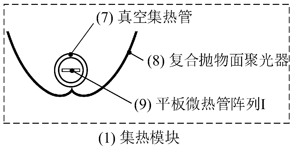
[0035] figure 2 It is a structural schematic diagram of th...


PUM

PropertyMeasurementUnit
diameteraaaaaaaaaa

Abstract

The invention discloses a compound parabolic concentrating power generation-phase change heat storage device and belongs to the field of solar energy heat utilization and solar energy thermoelectric power generation. The device is composed of a heat collecting module (composed of an evacuated solar collector tube, a compound parabolic condenser and a flat miniature heat pipe array), a power generation module (composed of the flat miniature heat pipe array and a thermoelectric power generation piece), a heat storage module (composed of a flat miniature heat pipe, heat exchanging fins, a heat storage material and a heat storage box body), and a cooling water pipe, wherein the flat miniature heat pipe array component is used as a heat transmission conductor in the device; heat received by a vacuum tube can be rapidly transmitted to a first power generation module by the flat miniature heat pipe array, the flat miniature heat pipe array and the heat storage module jointly provide temperature difference for the first power generation module to generate electricity energy; in addition, the heat storage module can provide a heat source for a second power generation module; the heat storage module and a cooling module jointly provide temperature difference for the second power generation module and generate electricity energy and heat energy; and the electricity energy generated by thefirst and second power generation modules can be directly consumed by electric equipment or is stored through a storage battery.

Description

technical field [0001] The invention relates to a composite parabolic concentrating power generation-phase change heat storage device, which belongs to the fields of solar thermal utilization and solar thermal power generation. Background technique [0002] Solar energy is generally considered to be one of the most ideal clean and renewable energy sources. Proper use can fully reduce the dependence on traditional fossil energy sources, thereby alleviating the energy crisis and my country's environmental pollution problems. Solar thermal power generation technology is an energy conversion technology that uses thermoelectric conversion materials to use solar energy as a heat source for thermoelectric materials, and an external cold source is placed at the other end of the thermoelectric materials to generate electrical energy. It has no mechanical rotating parts, simple structure, and small size. , Simple manufacturing process, low operating cost, long life, no noise and littl...

Claims


Application Information

Patent Timeline
Patent Type & Authority Applications(China)
IPC IPC(8): F24S10/40F24S23/71F24S60/30F24S70/20H02S40/44
CPCF24S10/40F24S23/71F24S60/30F24S70/20H02S40/44Y02E10/44Y02E10/50Y02E10/60
Inventor 刁彦华王泽宇赵耀华梁林
Owner BEIJING UNIV OF TECH
Why Eureka
Try Eureka