Refrigerating equipment and valve control method thereof

A refrigeration equipment and valve control technology, applied in the field of air-conditioning refrigeration equipment, refrigeration equipment and valve control, can solve problems such as unsatisfactory energy saving effect, increased burden of energy consumption loss of data room air-conditioning refrigeration system, single refrigeration form of refrigeration system, etc. , to achieve the effect of eliminating work energy consumption, reducing work energy consumption and saving power resources

Active Publication Date: 2015-03-18
CHINA ENERGY CONSTR GRP SHAANXI ELECTRIC POWER DESIGN INST CO LTD
View PDF3 Cites 0 Cited by
  • Summary
  • Abstract
  • Description
  • Claims
  • Application Information

AI Technical Summary

Problems solved by technology

The construction of large-scale data computer rooms has made various industries put forward high requirements for the concealment, safety and reliability of data computer rooms. At the same time, the huge energy consumption loss of air conditioning and refrigeration systems in data computer rooms has also added a lot of burden to various industries.
[0003] In order to meet the needs of social development and the national energy-saving policy, there are a wide variety of energy-saving products and various energy-saving measures, but the refrigeration system and refrigeration form are single. These technologies or products often increase the initial investment of the project a lot, but the energy-saving effect is not ideal.

Method used


Image

  • Refrigerating equipment and valve control method thereof

Examples


Embodiment

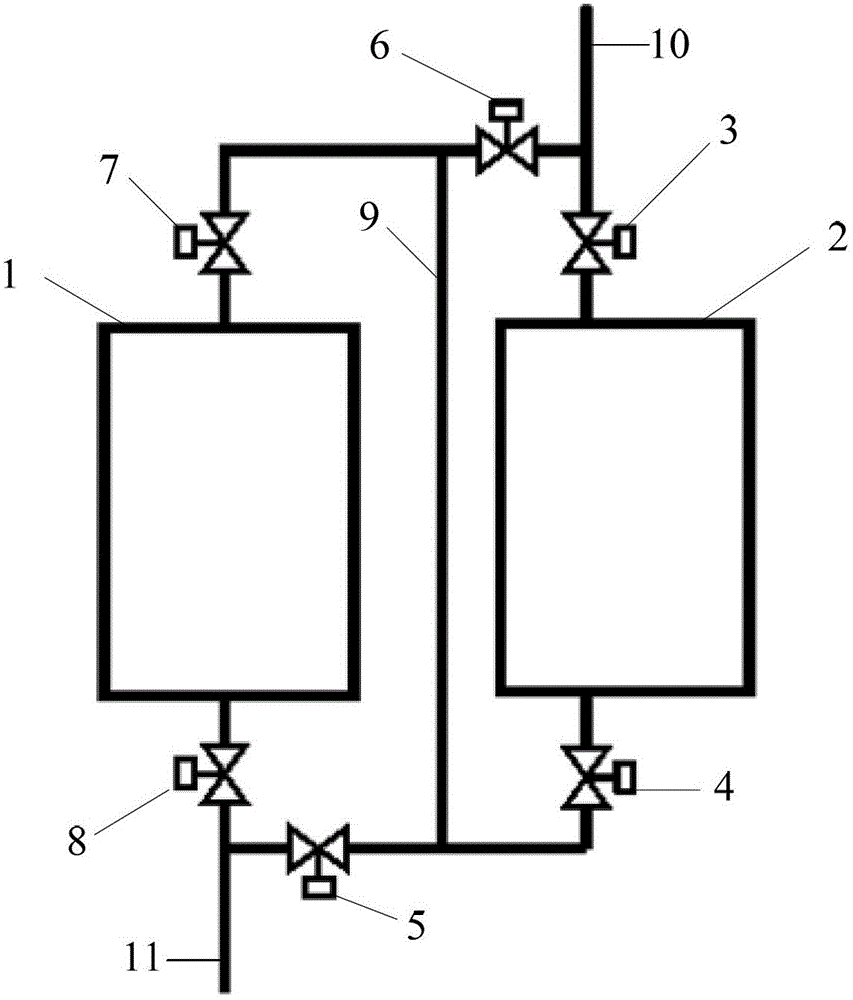
[0028] The following is based on figure 1 , taking the desired cooling water temperature as 7 / 12°C as an example, the valve control method of the present invention is further described:

[0029] When the outdoor temperature is high in summer, that is, the wet bulb temperature is ≥ 8 °C, and the cooling water temperature is ≥ 12 °C, the mode where only the evaporator 1 works is adopted, that is, the heat exchanger inlet valve 3, the heat exchanger outlet valve 4 and the Water supply switching control valve 5, open the other valves; the desired cooling water enters the refrigeration equipment through the water inlet pipe 10, flows through the return water switching control valve 6, the evaporator inlet valve 7, and reaches the evaporator 1 for cooling. The outlet flows out, and flows out of the refrigeration equipment through the evaporator outlet valve 8 to the water outlet pipe 11.

[0030] When the outdoor temperature is very low in winter, that is, the outdoor temperature i...


PUM


Abstract

The invention discloses refrigerating equipment and a valve control method thereof. The refrigerating equipment comprises an evaporator and a heat exchanger, wherein a water inlet of the evaporator is connected with that of the heat exchanger through a pipeline; an evaporator inlet valve, a water return switching control valve and a heat exchanger inlet valve are arranged on the pipeline from the water inlet of the evaporator and the water inlet of the heat exchanger in sequence; a water outlet of the evaporator is connected with that of the heat exchanger through the pipeline; an evaporator outlet valve, a water supply switching control valve and a heat exchanger outlet valve are arranged on the pipeline from the water outlet of the evaporator and the water outlet of the heat exchanger in sequence; and a cross pipeline is led out from the pipeline between the evaporator inlet valve and the water return switching control valve and is connected to the pipeline between the water supply switching control valve and the heat exchanger outlet valve. The refrigerating equipment is formed in such a way that the heat exchanger is additionally arranged in a water-cooled chiller and the general evaporator, the heat exchanger, the pipelines, the valves and others are connected; and the evaporator and the heat exchanger are controlled, so that the cooling temperature difference of the evaporator is reduced, the working energy consumption of the refrigerating compressor is effectively reduced, and the electric resource is greatly saved.

Description

technical field [0001] The invention belongs to the field of air-conditioning and refrigeration, and relates to an air-conditioning refrigeration device, in particular to a refrigeration equipment and a valve control method thereof. Background technique [0002] With the development of society and the improvement of people's living standards, various industries such as finance, network, communication, and electric power have experienced a trend of large data concentration. The construction of large-scale data room has made various industries put forward high requirements for the concealment, safety and reliability of the data room. At the same time, the huge energy consumption loss of the air conditioning and refrigeration system of the data room has also added a lot of burden to various industries. [0003] In order to meet the needs of social development and the national energy-saving policy, there are a wide variety of energy-saving products and various energy-saving meas...

Claims


Application Information

Patent Timeline
Patent Type & Authority Patents(China)
IPC IPC(8): F25B41/04F25B49/02
Inventor 李秀璋韩永兴王胜利张海刚许万军屈克吴建华韩炘高明鹏
Owner CHINA ENERGY CONSTR GRP SHAANXI ELECTRIC POWER DESIGN INST CO LTD
Why Eureka
Try Eureka