Steady-state evoked potential brain-computer interface method based on motion turning vision sensing

A steady-state induction and visual perception technology, applied in the fields of neural engineering and brain-computer interface, can solve the problems of users' visual fatigue, long stimulus presentation time, and the reduction of user's brain response signal, so as to ensure efficient transmission, brain-computer interface, etc. The effect of being friendly to the computer interaction process, avoiding neural adaptation and reducing the brain response signal

Active Publication Date: 2012-10-10
西安臻泰智能科技有限公司
View PDF11 Cites 23 Cited by
  • Summary
  • Abstract
  • Description
  • Claims
  • Application Information

AI Technical Summary

Problems solved by technology

But the disadvantage is that the visual homeostasis evoked potential relies on the visual stimulation generated by light flicker to induce, which requires a strong light intensity, which is likely to cause discomfort to the user; especially at a lower stimulation frequency, the light flicker cycle is longer, The brightness of the stimulation unit changes significantly in a single cycle, which is more likely to cause visual fatigue of the user and reduce the response signal of the user's brain. It is not suitable for long-term use of brain-computer interaction occasions.
In the field of brain-computer interaction, the Chinese patent "Human-computer interactio

Method used


Image

  • Steady-state evoked potential brain-computer interface method based on motion turning vision sensing
  • Steady-state evoked potential brain-computer interface method based on motion turning vision sensing
  • Steady-state evoked potential brain-computer interface method based on motion turning vision sensing

Examples


Embodiment Construction

[0042] The present invention will be further described in detail below in conjunction with the accompanying drawings and embodiments.

[0043] A steady-state evoked potential brain-computer interface method based on visual perception of motion reversal, comprising the following steps:

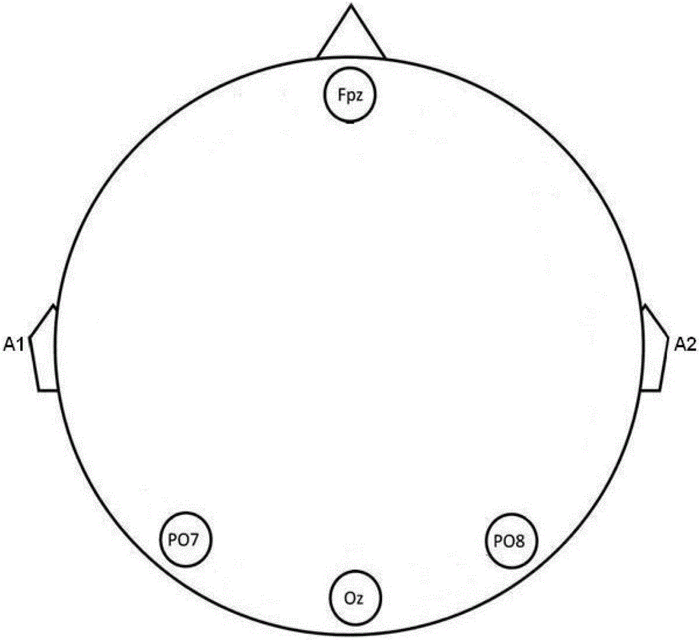
[0044] Step 1, refer to figure 1 , place measuring electrodes at PO7, Oz, and PO8 in the visual occipital area of ​​the user's head, place reference electrodes at A1 or A2 on one side of the earlobe, and place ground electrodes at Fpz on the forehead of the user's head. The electrical signal is sent to the computer after amplification and analog-to-digital conversion;

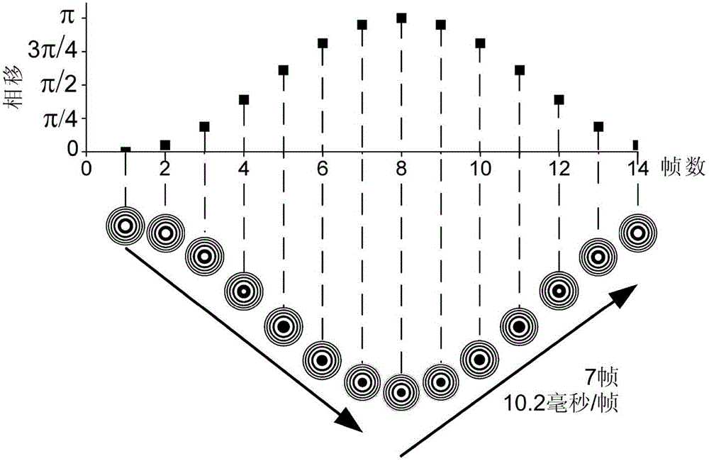
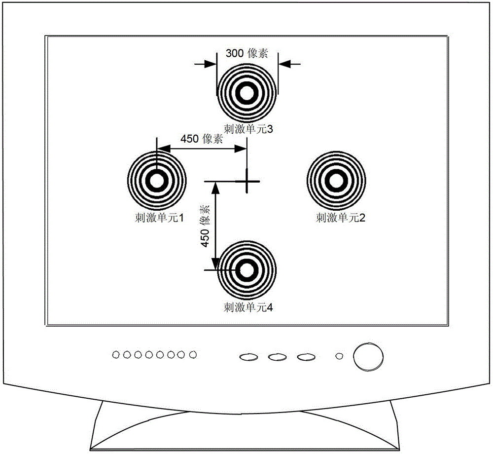
[0045] Step 2, refer to figure 2 with image 3 , four Newton ring motion stimulation units that carry out steady-state oscillatory motion according to different flipping frequencies are presented to the user through the computer screen at the same time. The left, right, up and down positions are displayed on the computer sc...


PUM


Abstract

A steady-state evoked potential brain-computer interface method based on motion turning vision sensing comprises the steps of arranging an electrode on the head of a user, measuring brain electric signals and sending the measured brain electric signals to a computer, then simultaneously showing newton ring motion stimulating units to the user by a computer screen, in the stimulation showing process, contracting and expanding the newton ring motion stimulating units according to a sine modulation mode so as to form periodical reciprocating motion in two directions, after the newton ring motion stimulating units are formed, enabling the user to stare any one of the newton ring motion stimulating units, synchronously acquiring a stimulating start position and a stimulating end position by the computer, acquiring the brain electric signals by a test electrode, calculating a stimulating target with the maximum related coefficient, judging and indicating the target through the screen, and then executing the next target recognizing task. The steady-state evoked potential brain-computer interface method has the characteristics of low flickering rate and low adaptability, can not result in visual fatigue of the user and the reduction of brain response signals, and is suitable for occasions needing brain-computer interaction for a long time.

Description

technical field [0001] The invention relates to the technical fields of neuroengineering and brain-computer interface in biomedical engineering, in particular to a steady-state evoked potential brain-computer interface method based on motion reversal visual perception. Background technique [0002] Brain-computer interface is the abbreviation of human brain-computer interface. As an important information carrier of brain-computer interface, visual homeostasis evoked potential signal has the advantages of P300, event-related synchronization / desynchronization, spontaneous EEG signal, etc. Strong anti-interference ability, high information transmission rate, and the characteristics that all users can induce strong signals without training, so it is the most practical type of signal in all brain-computer interface systems. But the disadvantage is that the visual homeostasis evoked potential relies on the visual stimulation generated by light flicker to induce, which requires a s...

Claims


Application Information

Patent Timeline
IPC IPC(8): G06F3/01
Inventor 徐光华谢俊张锋王晶李黎黎
Owner 西安臻泰智能科技有限公司
Why Eureka
Try Eureka