Low-temperature insulator and manufacturing method thereof

A low-temperature insulator, main insulation technology, applied in insulators, lead-in/punch-through insulators, usage of superconductor elements, etc., can solve problems such as poor reliability and damage, and achieve low cost, improved reliability, and good low-temperature sealing performance. Effect

Inactive Publication Date: 2012-10-10
HARBIN INST OF TECH
View PDF7 Cites 4 Cited by
  • Summary
  • Abstract
  • Description
  • Claims
  • Application Information

AI Technical Summary

Problems solved by technology

[0004] The object of the present invention is to provide a low-temperature insulator and its manufacturing method, so as to solve the problem that the low-temperature sealing performance of the low-temperature insulator is easily damaged by tensile stress, bending stress and torsional stress in all temperature zones where the temperature can be lowered, as well as its repeated cooling. The problem of poor reliability after cycling

Method used


Image

  • Low-temperature insulator and manufacturing method thereof
  • Low-temperature insulator and manufacturing method thereof
  • Low-temperature insulator and manufacturing method thereof

Examples


specific Embodiment approach 1

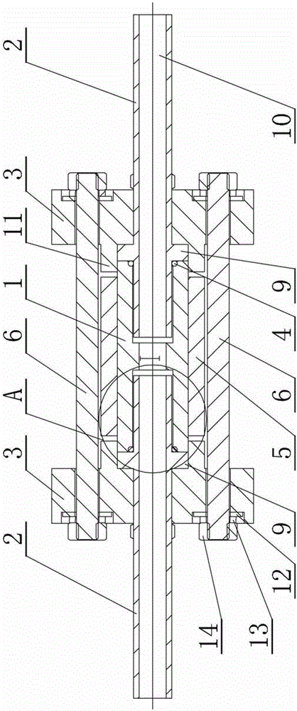
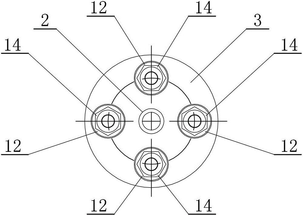
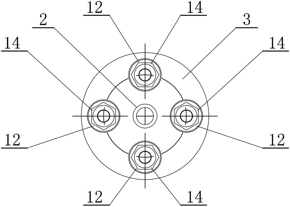
[0015] Specific implementation mode one: combine figure 1 , figure 2 , image 3 with Figure 4 This embodiment is described. The low-temperature insulator described in this embodiment includes a main insulating pipe 1, a sleeve 5, two connecting pipes 2, two insulating pressure plates 3, two indium rings 4 and four tension screws 6. The sleeve 5 is set on the outer surface of the main insulating pipe 1, and the two ends of the main insulating pipe 1 are respectively provided with an insulating pressure plate 3 and a connecting pipe 2, and each insulating pressure plate 3 is processed with an axial through hole 7 and four tie rods Through holes 8, each connecting pipe 2 is respectively processed with a shoulder 9, each connecting pipe 2 passes through the axial through hole 7 on the corresponding insulating pressure plate 3 and is fixedly connected to the inside of the main insulating pipe 1, each connecting pipe The shoulder 9 on 2 is in close contact with the main insulat...

specific Embodiment approach 2

[0016] Specific implementation mode two: combination figure 1 Note that in this embodiment, the length of the connecting pipe 2 located outside the main insulating pipe 1 is 30-40 mm, and the length of the connecting pipe 2 located inside the main insulating pipe 1 is 15-20 mm. Other components and connections are the same as those in the first embodiment.

specific Embodiment approach 3

[0017] Specific implementation mode three: combination figure 1 Note that, in this embodiment, the inner diameter of each connecting pipe 2 is less than 5 mm, and the outer diameter of each connecting pipe 2 is less than 7 mm. Such size setting can not only ensure sufficient flow of cryogenic fluid to flow to the current leads, but also minimize the area of ​​the insulating sealing interface. Other compositions and connections are the same as those in Embodiment 1 or 2.


PUM

PropertyMeasurementUnit
lengthaaaaaaaaaa
thicknessaaaaaaaaaa
diameteraaaaaaaaaa

Abstract

The invention relates to a sealing device and a manufacturing method thereof, and particularly relates to a low-temperature insulator and a manufacturing method thereof. The invention aims to solve the problems that the low-temperature sealing performance of the low-temperature insulator is likely to be affected by tensile stress, bending stress and torsional stress in all warm areas, and the reliability of the insulator after repeated cooling and heat cycle is low. A sleeve is sleeved on the outer surface of a main insulating tube; an insulating pressure plate and an adapter tube are arranged at each end of the main insulating tube; each insulating pressure plate is provided with an axial through hole and four pull rod through holes; each adapter tube is provided with a ledge, passes through the axial through hole on the corresponding insulating pressure plate and is fixedly connected inside the main insulating tube; the ledge on each adapter tube is attached to the main insulating tube; the insides of the two adapter tubes and the main insulating tube are communicated to form an airflow passage; four tensioning screws are arranged between the two insulating pressure plates; and an indium ring is arranged between the main insulating tube and the ledge of the adapter tube. The low-temperature insulator is used for low-temperature pipelines.

Description

technical field [0001] The invention relates to a sealing device and a manufacturing method thereof, in particular to a low-temperature insulator and a manufacturing method thereof. Background technique [0002] With the maturity of materials and manufacturing processes, the stability of superconducting magnets has been continuously enhanced to the point where it is no longer a concern. Liquid helium, which is used to obtain the low-temperature operation conditions of superconducting magnets, is a scarce resource on the earth, and its price continues to rise. Therefore, many superconducting magnets that have been industrialized, such as large-diameter superconducting magnets (diameter greater than 0.5m) such as nuclear magnetic resonance superconducting magnets, are looking for design solutions with less liquid helium and less liquid helium. Compared with immersion cooling, indirect cooling superconducting magnets have the advantages of less resident liquid helium and less ...

Claims


Application Information

Patent Timeline
Patent Type & Authority Applications(China)
IPC IPC(8): H01B17/30H01B19/00H01B12/00
CPCY02E40/64Y02E40/60
Inventor 徐风雨陈安斌
Owner HARBIN INST OF TECH
Why Eureka
Try Eureka