
Broadband annular oscillator

A ring oscillator and broadband technology, applied in the field of microelectronics, can solve the problems of stability and reliability of the ring oscillator frequency stability, and achieve the effect of low power consumption and low system power consumption

Inactive Publication Date: 2012-10-10
HANGZHOU DIANZI UNIV
View PDF10 Cites 9 Cited by
  • Summary
  • Abstract
  • Description
  • Claims
  • Application Information

AI Technical Summary

Problems solved by technology

The above two structures both use two bias voltages to be controlled at the same time, and the two bias voltages are controlled by the voltage output by the previous stage loop filter, so the stability and reliability of the bias voltage generating circuit have a great influence on the frequency of the ring oscillator. Stability has a big impact

Method used


Image

  • Broadband annular oscillator
  • Broadband annular oscillator
  • Broadband annular oscillator

Examples


Embodiment Construction

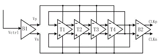
[0019] like figure 1As shown, a broadband ring oscillator includes a voltage bias unit B1, a buffer unit B2 and four delay units T1-T4.

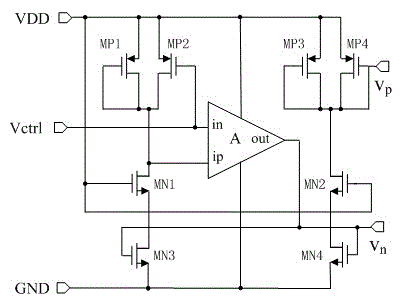
[0020] The input terminal Vctrl of the voltage bias unit B1 is connected to an external input signal, the PMOS voltage bias terminals Vp of the four delay units T1-T4 are connected to the PMOS voltage bias terminal Vp of the voltage bias unit B1, and the PMOS voltage bias terminals Vp of the four delay units T1-T4 The NMOS voltage bias terminal Vn and the voltage bias terminal Vn of the buffer unit B2 are connected to the NMOS voltage bias terminal Vn of the voltage bias unit B1; the non-inverting output terminal op of the first delay unit T1 is connected to the non-inverting input terminal of the second delay unit T2 ip, the non-inverting output terminal op of the second delay unit T2 is connected to the non-inverting input terminal ip of the third delay unit T3, the non-inverting output terminal op of the third delay unit T3 is connected t...


PUM


Abstract

The invention relates to a broadband annular oscillator. Inverters of single end structure are currently used as the delay units of the broadband annular oscillator, wherein the delay units are subject to the interference of substrate coupling noise. The broadband annular oscillator of the invention comprises a voltage offset unit, a buffer unit, and four delay units connected in series. A phase shift of 180 degrees is realized from the input terminal of the first delay unit to the output terminal of the fourth delay unit. The input terminal of the voltage offset unit is connected to external input signals. The PMOS voltage offset terminals of the four delay units is connected to the PMOS voltage offset terminal of the voltage offset unit. The NMOS voltage offset terminals of the four delay units and the voltage offset terminal of the buffer unit are connected to the NMOS voltage offset terminal of the voltage offset unit. The in-phase output terminal of the buffer unit is used as an in-phase clock output pin, and the anti-phase output terminal of the buffer unit is used as an anti-phase clock output pin. According to the invention, the interference from a voltage offset circuit on the frequency of the oscillator is isolated, low-jitter clock signal outputting can be realized, and a multiprotocol multiterminal communication requirement can be satisfied.

Description

technical field [0001] The invention belongs to the technical field of microelectronics and relates to a broadband ring oscillator. Background technique [0002] In recent years, electronic products are required to be able to meet the requirements of handheld multi-terminal communication, and almost all communication systems require a stable periodic signal, namely a clock, to provide the basic timing basis. These clock signals are typically generated by frequency synthesis techniques. The core of frequency synthesis technology is oscillator circuit design. In order to meet the requirements of multi-protocol mobile terminal communication, designing an oscillator with low power consumption and wide frequency band becomes the key to realize high-performance clock signal. Commonly used structures for oscillators are LC oscillators and ring oscillators. LC oscillators require on-chip integration of LCs, and broadband structures require capacitive switch arrays. However, the ...

Claims


Application Information

Patent Timeline
Patent Type & Authority Applications(China)
IPC IPC(8): H03B5/04H03K3/011
Inventor 周明珠孙玲玲
Owner HANGZHOU DIANZI UNIV
Learn More