Proportional timing sampling circuit and switch power source using same

A timing sampling and switching technology, applied in the connection/interface layout of logic circuits, the coupling/interface of logic circuits using field effect transistors, electrical components, etc. , the effect of high-precision constant voltage output

Active Publication Date: 2014-11-19
DALIAN LIANSHUN ELECTRONICS +3
View PDF4 Cites 0 Cited by
  • Summary
  • Abstract
  • Description
  • Claims
  • Application Information

AI Technical Summary

Problems solved by technology

As a result, the precision of the constant voltage output Vo of the switching power supply is not high
[0005] The internal sampling circuit of the traditional controller 20 also adopts a regular sampling method, and when the feedback winding signal 33 changes, sampling errors will also occur, such as figure 2 As shown in (b), the accuracy of the constant voltage output Vo of the switching power supply is not high

Method used


Image

  • Proportional timing sampling circuit and switch power source using same
  • Proportional timing sampling circuit and switch power source using same
  • Proportional timing sampling circuit and switch power source using same

Examples


Embodiment Construction

[0046] The utility model will be further described below in conjunction with the accompanying drawings and examples of implementation.

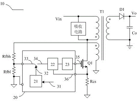
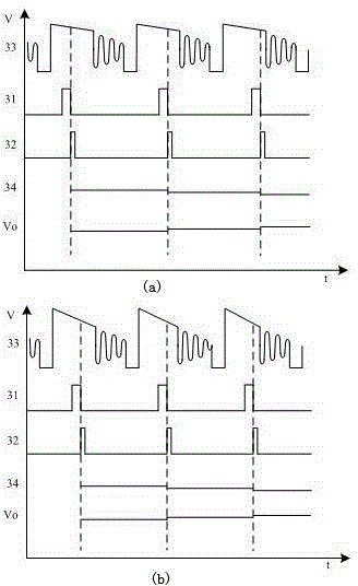
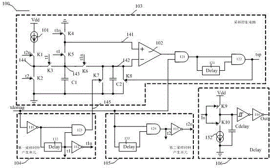
[0047] The invention discloses a proportional timing sampling circuit, which is characterized in that it is composed of a sampling control circuit, a first sampling clock generation unit, a second sampling clock generation unit and a delay unit, which are sequentially electrically connected. For details, see image 3 , image 3 It is a circuit connection schematic diagram of the proportional timing sampling circuit of the present embodiment, the input terminal of the proportional timing sampling circuit described in the figure is connected with the tdemag signal, the output terminal is connected with the output terminal of the second AND gate 122, and the first bias current source 101 is connected to the upper plate 143 of the first capacitor C1 through the first switch K1 and the third switch K3, the upper plate 143 of the first capacitor C1...


PUM


Abstract

The invention relates to a proportional timing sampling circuit and a switch power source using the same. The proportional timing sampling circuit is formed by sequentially electrically connecting a sampling control circuit, a first sampling clock generation unit, a second sampling clock generation unit and a relay unit. Precise and proportional sampling can be realized by setting the ratio of two capacitors, and timing sampling along with system demagnetization time can be realized. The switch power source comprises a transformer and a control circuit and is characterized in that the pulse width and frequency of the transformer can be precisely adjusted by means of timing proportional sampling of a feedback winding unit of the transformer by the control circuit, the control circuit comprises the proportional timing sampling circuit, and high constant-voltage output precision can be achieved by the switch power source.

Description

technical field [0001] The invention relates to a proportional timing sampling circuit and a switching power supply using the sampling circuit. Background technique [0002] Switching power supplies using traditional controllers such as figure 1 As shown, the switching power supply includes an output module connected to both ends of the secondary winding of the transformer T1, a sink circuit connected to both ends of the main winding of the transformer T1, the drain of the switching tube Q1 is connected to one end of the main winding, and the gate is connected to the traditional controller 20 The output end is connected, the source is connected with the sampling resistor Rcs, the controller 20, and the feedback winding unit is connected with the controller; the controller includes a sampling switch and a sampling circuit 32, and the feedback winding unit is connected with the PWM / PFM modulator 22; PWM / The PFM modulator 22 is connected to the sampling resistor Rcs and the l...

Claims


Application Information

Patent Timeline
Patent Type & Authority Patents(China)
IPC IPC(8): H03K19/0185H02M3/335
Inventor 高耿辉叶英王利李铎
Owner DALIAN LIANSHUN ELECTRONICS
Why Eureka
Try Eureka