Method and apparatus for measuring carrier

A carrier and measurement result technology, which is applied to the separation device of the transmission path, digital transmission system, electrical components, etc., can solve the problems of rising UE chip cost, not knowing the configuration of uplink and downlink subframes of the carrier, and increasing UE measurement hardware resources, etc. To achieve the effect of improving efficiency

Active Publication Date: 2012-10-10
HONOR DEVICE CO LTD
3 Cites 9 Cited by

AI-Extracted Technical Summary

Problems solved by technology

[0009] When the uplink and downlink subframe configurations of the carriers are different, although the UE knows the uplink and downlink subframe configurations of the currently serving carrier (including the carrier on which the UE camps in idle mode and the carrier from which the UE receives services in connected mode), However, the UE does not know the uplink and downlink subframe configuration of the carriers that are not currently providing services, so the UE's measurement of these carriers that are not currently providing services will be affected
For example, in the DRX (Discontinuous reception, discontinuous reception) state, since the UE can only measure the carrier that is not currently providing services for the subframe 0 and the subframe 5 in each configuration mode ...

Method used

According to the method for measuring the carrier provided by the embodiment of the present invention, according to the uplink and downlink subframe configuration information of the non-current service carrier obtained from the control message, the uplink and downlink subframe configuration of the non-current serving carrier can be determined, so that More downlink subframes are used to measure the carriers that are not currently providing services. Optionally, in addition to the downlink subframe, a special subframe (such as S in Table 1) may also be used to measure a carrier that is not currently providing services. Compared with related technologies that only use subframes No. 0 and No. 5 for measurement, more subframe information can be used to obtain more accurate measurement results in a shorter time, thereby improving the efficiency of measuring carriers. And since the measurement process is still performed based on subframes, there is no need to increase the hardware resources required for UE measurement, which will ...

Abstract

The embodiment of the invention provides a method and an apparatus for measuring carrier. The method comprises: receiving a control message from a base station, wherein the control message being used for indicating up-down subframe configuration of the carrier not currently providing services; determining the uplink-downlink configuration of the carrier not currently providing services based on the control message; and measuring the carrier based on the uplink-downlink configuration of the carrier. The apparatus comprises a reception module, a determination module, and a measuring module. Based on the technical scheme provided by the embodiment of the invention, the uplink-downlink configuration of the carrier not currently providing services can be obtained from the control message, so that more subframe information can be used for measuring the carrier not currently providing services, and more accurate measure results can be obtained in a shorter time, efficiency of measuring the carrier is improved, and the measurement process is still carried out based on the subframe, hardware resources needed for measuring by the user equipment need not to be increased, thereby preventing the cost of the chip of the user equipment from rising.

Application Domain

Error preventionTransmission path division +1

Technology Topic

Carrier signalSubframe +3

Image

  • Method and apparatus for measuring carrier
  • Method and apparatus for measuring carrier
  • Method and apparatus for measuring carrier

Examples

  • Experimental program(1)

Example Embodiment

[0021] The technical solutions of the embodiments of the present invention will be clearly and completely described below with reference to the accompanying drawings in the embodiments of the present invention. Obviously, the described embodiments are part of the embodiments of the present invention, but not all of the embodiments. Based on the embodiments of the present invention, all other embodiments obtained by those skilled in the art without creative work shall fall within the protection scope of the present invention.
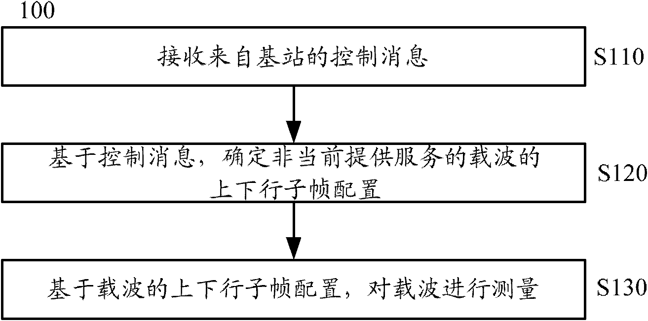
[0022] First, combine figure 1 A method 100 of measuring a carrier according to an embodiment of the present invention is described.
[0023] like figure 1 As shown, the method 100 includes: in S110, receiving a control message from a base station, where the control message is used to indicate an uplink and downlink subframe configuration of a carrier that is not currently providing services; in S120, based on the control message, determining The configuration of the uplink and downlink subframes of the carrier; in S130, based on the configuration of the uplink and downlink subframes of the carrier that is not currently providing the service, the measurement is performed on the carrier that is not currently providing the service.
[0024] The UE may receive a control message from the base station, and the control message may carry uplink and downlink subframe configuration information of other carriers except the carrier currently serving the UE, to indicate the uplink and downlink subframe configuration of the corresponding carrier. According to the control message, the UE may acquire the configuration information of the uplink and downlink subframes of the carrier that is not currently providing the service. A carrier that is not currently serving is a carrier that does not currently serve the UE, which may include a carrier that does not provide a service in the serving cell where the UE is located, or a carrier of a neighbor cell adjacent to the serving cell. The carrier that the UE camps on in idle mode or the carrier that the UE uses in connected mode belongs to the currently serving carrier, and the other carriers belong to the non-currently serving carrier. The UE can determine the uplink and downlink subframe configuration of the corresponding carrier according to the uplink and downlink subframe configuration information of the non-currently serving carrier, and thus can use more subframe information in the carrier to measure the carrier. The UE may determine the downlink subframes of the carrier based on the configuration of the uplink and downlink subframes of the carrier, so as to measure the carrier on these downlink subframes.
[0025] According to the method for measuring a carrier provided by the embodiment of the present invention, the uplink and downlink subframe configuration of the non-current serving carrier can be determined according to the uplink and downlink subframe configuration information of the non-currently serving carrier obtained from the control message, so that more downlink subframes to measure the carrier that is not currently serving. Optionally, in addition to the downlink subframe, a special subframe (eg, S in Table 1) may also be used to measure a carrier that is not currently serving. Compared with the measurement performed only by using subframes 0 and 5 in the related art, more accurate measurement results can be obtained in a shorter time by using more subframe information, thereby improving the efficiency of measuring carriers. And because the measurement process is still performed based on subframes, there is no need to increase the hardware resources required for UE measurement, and the cost of UE chips will not increase.
[0026] Next, S110 to S130 according to the embodiment of the present invention are described in detail.
[0027] In S110, a control message from the base station is received, where the control message is used to indicate an uplink and downlink subframe configuration of a carrier that is not currently serving.
[0028] According to an embodiment of the present invention, the user equipment may receive system messages from the base station of the serving cell. The system message can carry the configuration information of the uplink and downlink subframes of the current serving carrier of the serving cell as in the related art, and can also be extended to carry carriers that are not currently serving (including other carriers and/or neighbors of the current serving cell) The uplink and downlink subframe configuration information of the carrier of the cell).
[0029] The base station of the serving cell where the UE is located may send a system message to the UE through a broadcast channel, and make the system message carry information related to a carrier that is not currently serving.
[0030]Carriers that are not currently serving include carriers that the UE is not camping on in idle mode, and carriers that are not used by the UE in connected mode. These carriers may include other carriers in the current serving cell except the carrier for receiving the system message, and may also include carriers in neighbor cells. These carriers may or may not have the function of carrier aggregation, so that these carriers that are not currently providing services may or may not be component carriers. The carriers that are not currently providing services involved in the system message may be all the carriers in the cell, or may be part of the carriers in the cell.
[0031] The uplink and downlink subframe configuration information of the carriers in the neighbor cell may be sent by the base station of the neighbor cell to the base station of the serving cell, and then sent to the user equipment by the base station of the serving cell.
[0032] There are various ways to carry the uplink and downlink subframe configuration information of the carrier in the system message. For example, the configuration information of the uplink and downlink subframes may be explicitly carried in the system message. For example, the information of whether the subframe of a specific subframe number is an uplink subframe (U) or a downlink subframe (D) is directly carried in the system message. The uplink and downlink subframe configuration information may also be carried by a specific identifier or number in the system message. For example, a certain number in the numbers 0 to 6 in Table 1 is carried in the system message, and the uplink and downlink subframe configuration information is represented by the number. The uplink and downlink subframe configuration information can also be defined by an enumeration type. Each value in the enumeration type corresponds to an uplink and downlink subframe configuration mode, and the uplink and downlink are represented by carrying a value belonging to the enumeration type in the system message. Subframe configuration information. In addition, the "TDD-Config" defined by the protocol may also be used directly to describe the TDD uplink and downlink subframe configuration information of the carrier.
[0033] According to an embodiment of the present invention, the user equipment may receive signaling from a base station of a serving cell, where the signaling carries uplink and downlink subframe configuration information of a carrier that is not currently serving.
[0034] For example, the user equipment may receive radio resource control (Radio Resource Control, RRC) signaling from the base station of the serving cell, and the RRC signaling may carry the uplink and downlink subframe configuration information of the current serving cell and the non-currently serving carrier in the neighbor cell . During the process of establishing the RRC connection or after the establishment of the RRC connection, the base station of the serving cell where the UE is located may send RRC signaling to the UE. In the RRC signaling, not only the uplink and downlink subframe configuration information of the non-currently serving carrier in the serving cell can be carried, but also the uplink and downlink subframe configuration information of the carrier in the neighbor cell can be carried. The uplink and downlink subframe configuration information of the carrier of the neighbor cell can still be transmitted by the base station of the neighbor cell to the base station of the serving cell. At this time, it is necessary to extend the RRC signaling, add new fields to the RRC signaling, or use the reserved fields in the RRC signaling to carry the uplink and downlink subframe configurations of the non-currently serving carriers based on the new fields or reserved fields. information. The way of carrying can refer to the above.
[0035] Of course, those skilled in the art can also easily think that, in addition to using RRC signaling to carry the uplink and downlink subframe configuration information of the carrier, other signaling or new redefined signaling can also be used to transmit non-currently provided services. The uplink and downlink subframe configuration information of the carrier, for example, use MAC (Media Access Control, medium access control) signaling or physical layer signaling.
[0036] As described above, the configuration information of the uplink and downlink subframes of the carriers that are not currently serving the serving cell and the neighbor cell may be carried in the system message or in the signaling. However, according to the embodiment of the present invention, when some carriers in the same frequency band have the same uplink and downlink subframe configuration, it is not necessary to carry the uplink and downlink subframe configuration information of all the carriers in the neighbor cell. For example, the system message or signaling may carry the uplink and downlink subframe configuration information of the carrier in the serving cell that is not currently serving; when the carrier in the neighbor cell has the same uplink and downlink subframe configuration as the carrier in the same frequency band in the serving cell , the system message or signaling may not carry the uplink and downlink subframe configuration information of the carrier of the neighbor cell. At this time, for the carriers in the neighbor cell, the system message or signaling can only carry the uplink and downlink subframe configuration information of those carriers whose uplink and downlink subframe configurations are unknown and whose uplink and downlink subframe configurations cannot be derived from the carriers in the same frequency band. .
[0037] Specifically, the system message or signaling needs to carry the uplink and downlink subframe configuration information of the carrier in the serving cell that is not currently providing services, but whether it needs to carry the uplink and downlink subframe configuration information of the carrier in the neighbor cell, it is necessary to carry the uplink and downlink subframe configuration information of the carrier in the neighbor cell. The relationship between the carriers in and the carriers in the serving cell is related. If the specific carrier of the neighbor cell and a certain carrier of the current serving cell are in the same frequency band and have the same uplink and downlink subframe configuration, it is not necessary to repeat the uplink and downlink subframe configuration of the specific carrier; If a specific carrier and a certain carrier of the current serving cell are on the same frequency band but have different uplink and downlink subframe configurations, the system message still needs to carry the uplink and downlink subframe configurations of the specific carrier; if the specific carrier of the neighbor cell If all carriers of the current serving cell are not on the same frequency band, the configuration of the uplink and downlink subframes of the specific carrier needs to be carried.
[0038] According to an embodiment of the present invention, the system message or signaling may carry the uplink and downlink subframe configuration information of the carrier in the serving cell that is not currently serving. At this time, when the non-currently providing service carrier in the neighbor cell and the non-currently providing service carrier in the serving cell have the same uplink and downlink subframe configuration, it can be based on the uplink and downlink subframe configuration of the non-currently providing service carrier in the serving cell. information to determine the configuration of the uplink and downlink subframes of the carriers that are not currently serving in the neighbor cell.
[0039] If a specific carrier in the neighbor cell has the same uplink and downlink subframe configuration as a certain carrier in the serving cell, the system message or signaling may not carry the uplink and downlink subframe configuration information of the specific carrier, but directly The carrier with the same uplink and downlink subframe configuration is used to obtain the uplink and downlink subframe configuration of the specific carrier.
[0040] According to an embodiment of the present invention, the user equipment can receive a system message from the base station of the serving cell, where the system message carries the configuration information of the uplink and downlink subframes of the carriers that are not currently serving in the serving cell; receive signaling from the base station of the serving cell , and the signaling carries the configuration information of the uplink and downlink subframes of the carrier that is not currently serving in the neighbor cell.
[0041] The order of receiving the system message and receiving the signaling does not limit the protection scope of the present invention.
[0042] When the UE is in idle (IDLE) mode, the UE can receive a system message from the base station of the serving cell. The system message not only contains the uplink and downlink subframe configuration information of the carrier the UE is currently camping on, but also contains the information about the subframe in the serving cell where the UE is located. The uplink and downlink subframe configuration information of other carriers. In this way, the UE can acquire the uplink and downlink subframe configuration of the carrier of the serving cell.
[0043] When the UE is in the connected mode (CONNECTED), the UE can acquire the uplink and downlink subframe configuration information of the carrier in the neighbor cell through signaling sent by the base station of the serving cell. The signaling may be RRC signaling or other signaling.
[0044] In this case, since the UE has already acquired the uplink and downlink subframe configuration information of the carrier of the serving cell in idle mode, it does not need to obtain the uplink and downlink subframe configuration information of the carrier of the serving cell through signaling, and only needs to use signaling It is sufficient to obtain the uplink and downlink subframe configuration information of the carrier of the neighbor cell. In the case of using signaling to obtain the uplink and downlink subframe configuration information of the carrier of the serving cell and the neighbor cell, since the system message may only contain the uplink and downlink subframe configuration information of the currently serving carrier, it is necessary to use signaling to obtain and The current serving carrier has related information of other carriers with different uplink and downlink subframe configurations.
[0045] In this embodiment, the system message carries the uplink and downlink subframe configuration information of the carrier in the serving cell, and the signaling can carry the uplink and downlink subframe configuration information of all the carriers in the neighbor cell. However, in the case that some carriers in the same frequency band have the same configuration of uplink and downlink subframes, the signaling may not carry the information of some carriers in the neighbor cell. According to an embodiment of the present invention, when the carrier in the neighbor cell has the same uplink and downlink subframe configuration as the carrier in the same frequency band in the serving cell, the signaling does not carry the uplink and downlink subframe configuration information of the carrier in the neighbor cell. At this time, the signaling only needs to carry the uplink and downlink subframe configuration information of the carrier whose uplink and downlink subframe configuration is unknown and cannot be derived from the carrier in the same frequency band.
[0046] According to an embodiment of the present invention, the user equipment may receive synchronization signals from base stations of a serving cell and/or a neighbor cell. The synchronization signal is sent by the base station on the synchronization channel, and the synchronization-related information is transmitted through the synchronization signal. The synchronization signal is sent periodically and continuously on the synchronization channel, and each period of the synchronization signal can be regarded as constituting a control message. The UE extracts the physical cell identification (PCI) in the synchronization signal by detecting the synchronization signal (ie, control message) sent by the base station of the neighbor cell on the synchronization channel, and determines the uplink and downlink subframe configuration information of the corresponding carrier according to the PCI. , which will be referred to below figure 2 to describe in detail.
[0047] In S120, based on the control message, determine the uplink and downlink subframe configuration of the carrier that is not currently providing service.
[0048] Through the control message received in S110, the uplink and downlink subframe configuration information of the carrier that is not currently providing service can be acquired, so that the uplink and downlink subframe configuration of the corresponding carrier can be determined. If the control message does not carry the uplink and downlink subframe configuration information of one or some carriers that are not currently providing services, it means that the carrier has the same uplink and downlink subframe configuration as a carrier with a known uplink and downlink subframe configuration in the same frequency band, This is still a conclusion based on control messages.
[0049] When the system message is received from the base station of the serving cell, the uplink and downlink subframe configurations of the carrier that is not currently providing service in the serving cell and the carrier of the neighbor cell can be directly determined through the system message. These non-currently providing service carriers may be all non-currently providing service carriers in the corresponding cell, or may be some non-currently providing service carriers in the corresponding cell. Through the system message, only the uplink and downlink subframe configurations of the carriers that are not currently providing services in the serving cell may be determined, and the uplink and downlink subframe configurations of the carriers in the neighbor cells are determined by means of signaling.
[0050] When receiving signaling such as RRC signaling from the base station of the serving cell, the uplink and downlink subframe configurations of the carriers that are not currently providing the serving carrier and the neighbor cells in the serving cell can be directly determined through the signaling. The uplink and downlink subframe configuration information of the carrier in the neighbor cell can also be determined only by signaling, and the uplink and downlink subframe configuration information of the non-currently serving carrier in the serving cell can be obtained by the UE through system messages in idle mode. For example, when the uplink and downlink subframe configuration information of the component carrier is carried through RRC signaling, if the system message sent by the base station corresponding to the component carrier currently serving the UE does not include the uplink and downlink of other component carriers in the cell where the base station is located If the configuration information of the uplink and downlink subframes is not required, the RRC signaling needs to carry the configuration information of the uplink and downlink subframes of the other component carriers of the cell, otherwise the RRC signaling may not carry the configuration information of the uplink and downlink subframes of the other component carriers of the cell, but only the neighbors. The configuration information of the uplink and downlink subframes of the constituent carriers in the cell. Specifically, in the RRC signaling, it can indicate whether the uplink and downlink subframe configurations of other component carriers are the same as the uplink and downlink subframe configurations of the current serving carrier (that is, the carrier where the UE resides). If they are different, it can be directly given. Its uplink and downlink subframe configuration information.
[0051] When the synchronization signal is received from the base station, the PCI of the corresponding carrier may be determined based on the synchronization signal. Since specific uplink and downlink subframe configuration information can be set for different PCIs in advance, the uplink and downlink subframe configuration information of the carrier can be determined according to the PCI of the carrier, such as figure 2 Described.
[0052] In S130, based on the uplink and downlink subframe configuration of the non-currently providing the service carrier, measure the non-currently providing the service carrier.
[0053]According to an embodiment of the present invention, the measurement of the non-currently serving carrier may be performed on the downlink subframe of the non-currently serving carrier based on the uplink and downlink subframe configuration of the non-currently serving carrier.
[0054] After determining the uplink and downlink subframe configuration information of the carrier that is not currently providing services, the uplink and downlink subframe configuration of the carrier can be determined, so that the specific position of the downlink subframe can be determined. In addition to the measurement, other downlink subframes may also be used to measure the carrier. Optionally, the carrier can also be measured using a special subframe.
[0055] According to the method for measuring a carrier provided by the embodiment of the present invention, by acquiring system information and/or signaling from the base station of the serving cell, the uplink and downlink subframe configuration of the carrier from which the user equipment does not receive service can be determined. In this way, in a system in which the carrier has different uplink and downlink subframe configurations, since the uplink and downlink subframe configurations of the carrier are determined, the UE can use more subframe information to assist in the carrier measurement, so compared with the related art, only 0 The measurement performed on the No. 1 and No. 5 subframes can obtain more accurate measurement results in a shorter time, thus improving the efficiency of measuring the carrier. In addition, the method for obtaining the configuration information of the uplink and downlink subframes of the carrier is simple, the existing system is not changed much, and the implementation complexity is low.
[0056] figure 2 It is a flowchart of a method 200 for measuring a carrier according to an embodiment of the present invention.
[0057] In S210, a synchronization signal from the base station is received.
[0058] The UE may receive the synchronization signal sent by the base station of the neighbor cell through the synchronization channel of the base station of the neighbor cell, and may also receive the synchronization signal sent by the base station of the serving cell through the synchronization channel of the base station of the serving cell. Through the synchronization signal sent by the base station, the UE can determine the synchronization information related to the carrier corresponding to the base station.
[0059] In S220, based on the synchronization signal, a physical cell identity of a carrier that is not currently serving is determined.
[0060] The synchronization signal sent by the base station through the synchronization channel carries the PCI information of the carrier used by the base station. Each carrier corresponds to a separate PCI. When the UE is still in the coverage of the base station of the serving cell, the UE may determine the PCI of the carrier in the serving cell according to the synchronization signal sent by the base station of the serving cell. When the UE is in an edge area between the serving cell and the neighbor cell, the UE can detect the carrier of the neighbor cell, and thus can determine the PCI of the detected carrier according to the synchronization signal sent from the base station of the neighbor cell.
[0061] In S230, the uplink and downlink subframe configuration of the carrier that is not currently providing service is determined based on the physical cell identifier.
[0062] A corresponding uplink and downlink subframe configuration mode may be set for each PCI in advance. In this way, according to the PCI of the carrier, the UE can determine the configuration of the uplink and downlink subframes of the carrier corresponding to the PCI.
[0063] Different PCIs may also be grouped in advance, and an uplink and downlink subframe configuration mode is set for each group. In this way, after the UE determines the PCI of the carrier in S220, the configuration of the uplink and downlink subframes corresponding to the group in which the PCI is located can be determined according to the group in which the PCI is located.
[0064] The base station can also dynamically allocate different uplink and downlink subframe configuration modes for the carriers, so that the uplink and downlink subframe configurations corresponding to each PCI can be dynamically changed. In this case, the base station of the serving cell can not only tell the UE the relationship between the PCI of its own carrier and the configuration of the uplink and downlink subframes, but also the PCI and the uplink and downlink subframes it obtains from the base station of the neighbor cell. The one-to-one correspondence of the configuration is notified to the UE. According to the PCI determined in S220, the UE can determine the uplink and downlink subframe configuration corresponding to the PCI, and thus can determine the uplink and downlink subframe configuration information corresponding to the carrier.
[0065] In S240, based on the uplink and downlink subframe configuration of the carrier that is not currently providing the service, the measurement is performed on the carrier that is not currently providing the service. This step is the same as figure 1 The S130 is basically the same.
[0066] Those skilled in the art can think that the method 200 can be used alone to obtain the uplink and downlink subframe configuration information of the carriers in the serving cell and the neighbor cell, and then measure the carriers in the serving cell and the neighbor cell, and the method 200 and the method 100 can also be performed combination to measure the carrier. For example, the uplink and downlink subframe configuration information of the carrier of the neighbor cell is acquired by the method 200, and then the carrier in the neighbor cell is measured, and the uplink and downlink subframe configuration information of the carrier of the serving cell is acquired by the system message or signaling in the method 100, Further, the carrier in the serving cell is measured.
[0067] According to the method for measuring the carrier provided by the embodiment of the present invention, the uplink and downlink subframe configuration of the carrier can be determined based on the correspondence between the PCI in the synchronization signal and the uplink and downlink subframe configuration by acquiring the synchronization signal from the base station. In this way, the configuration of the uplink and downlink subframes of the carrier can be conveniently determined according to the PCI information, so that more subframe information can be used to help measure the carrier. Measurement, more accurate measurement results can be obtained in a shorter time, so the efficiency of measuring the carrier can be improved. In addition, the method of acquiring the configuration information of the uplink and downlink subframes of the carrier is simple, and the existing messages and signaling do not need to be modified, and the implementation complexity is low.
[0068] Next, combine image 3 A method 300 of measuring a carrier according to an embodiment of the present invention is described.
[0069] S310 , S320 and S330 in the method 300 are substantially the same as S110 , S120 and S130 in the method 100 .
[0070] According to an embodiment of the present invention, after S330, the method 300 may further include S340, in the idle mode, when the carrier that the user equipment currently camps on cannot camp on, according to the measurement result, select a carrier that is not currently providing services The target carrier to camp on.
[0071] When the UE is in idle mode, the UE can determine the target carrier that can camp on according to the measurement of the carrier.
[0072] The UE may first measure the current serving carrier of the current serving cell, that is, measure the carrier on which the UE currently camps. If the quality of the currently camped carrier is lower than a certain threshold, it means that the currently camped carrier cannot be camped on, and then the measurement of other carriers of the serving cell is started. If other carriers in the serving cell are suitable for camping, this carrier is selected as a target carrier that can camp on. If a suitable campable carrier is still not found in other carriers of the serving cell, the measurement of the carrier of the neighbor cell is started. When a target carrier suitable for camping is found in a neighbor cell, the UE selects the carrier as a target carrier that can camp on, and determines to camp on the target carrier. If the target carrier suitable for camping selected by the UE is not in the same paging area as the carrier that the UE is currently camping on, the UE needs to perform a paging location update (Tracking Area Update, TAU) procedure.
[0073] According to an embodiment of the present invention, after S330, the method 300 may further include S350, in the connected mode, reporting the measurement result to the base station of the serving cell.
[0074] When the UE is in the connected mode, the UE that is in communication (for example, making a call, receiving data services, etc.) reports the measured signal quality of the carrier to the base station of the current serving cell, so that the base station of the serving cell can determine according to the result of the carrier measurement Whether to switch. The reported measurement result may include the measurement result of the carrier of the current serving cell and the measurement result of the carrier of the neighbor cell.
[0075] Although in image 3 S350 is executed after S340, but S350 may also be executed before S340, depending on the current state of the UE.
[0076] According to the method for measuring a carrier provided by the embodiment of the present invention, after a more accurate and fast measurement of the carrier is performed, the measurement result can be used according to the different modes in which the UE is located, thereby facilitating the execution of paging location update or handover.
[0077] The method for measuring a carrier according to an embodiment of the present invention has been described above, and the following will be combined with Figure 4 and Figure 5 An apparatus for measuring a carrier according to an embodiment of the present invention is described.
[0078] Figure 4 A structural block diagram of an apparatus 400 for measuring a carrier wave according to an embodiment of the present invention is shown.
[0079] The apparatus 400 includes a receiving module 410 , a determining module 420 and a measuring module 430 . The receiving module 410 may be an interface for receiving a control message from the base station, where the control message is used to indicate the configuration of the uplink and downlink subframes of the carrier that is not currently providing services. The determining module 420 may be configured to determine, based on the control message, an uplink and downlink subframe configuration of a carrier that is not currently serving. The measurement module 430 may be a processor, and may be configured to measure the non-currently serving carrier based on the uplink and downlink subframe configuration of the non-currently serving carrier.
[0080] For the above and other operations and/or functions of the receiving module 410, the determining module 420, and the measuring module 430, reference may be made to S110 to S130 in the method 100 for measuring a carrier, which is not repeated here to avoid repetition.
[0081] In the apparatus for measuring a carrier provided by the embodiment of the present invention, in a system in which the carriers have different uplink and downlink subframe configurations, these carriers can be determined according to the uplink and downlink subframe configuration information of the carriers that are not currently providing services obtained from the control message. Therefore, more downlink subframes can be used to measure the carriers that are not currently serving. Compared with the measurement performed only by using subframes 0 and 5 in the related art, more accurate measurement results can be obtained in a shorter time by using more subframe information, thereby improving the efficiency of measuring carriers. And because the measurement process is still performed based on subframes, there is no need to increase the hardware resources required for UE measurement, and the cost of UE chips will not increase.
[0082] Figure 5 A structural block diagram of another apparatus 500 for measuring a carrier according to an embodiment of the present invention is shown.
[0083] The receiving module 510 , the determining module 520 and the measuring module 530 of the apparatus 500 are basically the same as the receiving module 410 , the determining module 420 and the measuring module 430 of the apparatus 400 .
[0084] According to an embodiment of the present invention, the receiving module 510 may be configured to receive a system message or signaling from a base station of a serving cell, where the system message or signaling carries uplink and downlink subframe configuration information of a carrier that is not currently serving.
[0085] According to an embodiment of the present invention, the receiving module 510 may be configured to receive a system message or signaling from a base station of a serving cell, where the system message or signaling carries uplink and downlink subframe configuration information of a carrier that is not currently serving in the serving cell. At this time, the determining module 520 may also be configured to, when the non-currently providing service carrier in the neighbor cell and the non-currently providing service carrier in the serving cell have the same uplink and downlink subframe configuration, based on the non-currently providing service carrier in the serving cell The uplink and downlink subframe configuration information is used to determine the uplink and downlink subframe configuration of the carrier that is not currently providing services in the neighbor cell.
[0086]According to an embodiment of the present invention, the receiving module 510 may include a first receiving unit 512 and a second receiving unit 514, which may be different interfaces respectively. The first receiving unit 512 may be configured to receive a system message from a base station of a serving cell, where the system message carries uplink and downlink subframe configuration information of a carrier that is not currently serving in the serving cell. The second receiving unit 514 may be configured to receive signaling from the base station of the serving cell, where the signaling carries uplink and downlink subframe configuration information of a carrier in a neighbor cell that is not currently serving.
[0087] According to an embodiment of the present invention, the receiving module 510 may be configured to receive a synchronization signal from a base station. At this time, the control message is a synchronization signal, and the determination module 520 may include a first determination unit 522 and a second determination unit 524 . The first determining unit 522 may be configured to determine the physical cell identity of the carrier based on the synchronization signal. The second determining unit 524 may be configured to determine the uplink and downlink subframe configuration information of the carrier based on the physical cell identifier.
[0088] According to an embodiment of the present invention, the apparatus 500 may further include at least one of a selection module 540 and a reporting module 550, and the two modules may be processors. The selection module 540 may be configured to, in the idle mode, select a target carrier that can camp on among the carriers that are not currently serving according to the measurement result when the carrier on which the user equipment currently camps cannot camp. The reporting module 550 may be configured to report the measurement result to the base station of the serving cell in the connected mode.
[0089] According to an embodiment of the present invention, the measurement module 530 may be configured to measure the non-currently serving carrier on the downlink subframe of the non-currently serving carrier based on the uplink and downlink subframe configuration of the non-currently serving carrier.
[0090] The above and other operations and/ Or the functions may refer to S110 to S130 in the method 100 for measuring a carrier, S210 to S230 in the method 200, and S340 and S350 in the method 300. To avoid repetition, details are not described here.
[0091] The apparatus for measuring the carrier provided by the embodiment of the present invention can determine the uplink and downlink subframe configuration information of the carrier from which the user equipment does not receive the service by acquiring system information and/or signaling from the base station of the serving cell. The uplink and downlink subframe configuration of the corresponding carrier can also be determined based on the correspondence between the PCI in the synchronization signal and the uplink and downlink subframe configuration by acquiring the synchronization signal from the base station of the serving cell and/or the neighbor cell.
[0092] In this way, in a system in which the carrier has different uplink and downlink subframe configurations, since the uplink and downlink subframe configurations of the carrier are determined, the UE can use more subframe information to assist in the carrier measurement, so compared with the related art, only 0 The measurement performed on the No. 1 and No. 5 subframes can obtain more accurate measurement results in a shorter time, thus improving the efficiency of measuring the carrier. In addition, the method of acquiring the uplink and downlink subframe configuration information of the carrier is simple and easy, and the existing system is not changed much, especially in the case of using the PCI to acquire the uplink and downlink subframe configuration information of the corresponding carrier, there is no need for existing messages and information. order to be modified so that the implementation complexity is low.
[0093] In addition, after more accurate and fast measurement of the carrier is performed, the measurement result can be used according to the different modes in which the apparatus provided in the embodiment of the present invention is located, thereby facilitating the execution of paging location update or handover.
[0094] Those skilled in the art can realize that, in combination with the method steps and units described in the embodiments disclosed herein, they can be implemented by electronic hardware, computer software, or a combination of the two, in order to clearly illustrate the interoperability of hardware and software Alternatively, the steps and components of each embodiment have been generally described in terms of their functions in the foregoing description. Whether these functions are performed in hardware or software depends on the specific application and design constraints of the technical solution. Skilled artisans may implement the described functionality in varying ways for each particular application, but such implementations should not be considered beyond the scope of the present invention.
[0095] The method steps described in connection with the embodiments disclosed herein may be implemented in hardware, a software program executed by a processor, or a combination of the two. The software program can be placed in random access memory (RAM), internal memory, read only memory (ROM), electrically programmable ROM, electrically erasable programmable ROM, registers, hard disk, removable disk, CD-ROM or in the technical field in any other known form of storage medium.
[0096] Although some embodiments of the present invention have been shown and described, it should be understood by those skilled in the art that various modifications may be made to these embodiments without departing from the principle and spirit of the invention, such modifications should be within the scope of the present invention.

PUM

no PUM

Description & Claims & Application Information

We can also present the details of the Description, Claims and Application information to help users get a comprehensive understanding of the technical details of the patent, such as background art, summary of invention, brief description of drawings, description of embodiments, and other original content. On the other hand, users can also determine the specific scope of protection of the technology through the list of claims; as well as understand the changes in the life cycle of the technology with the presentation of the patent timeline. Login to view more.

Similar technology patents

Control circuit and method for a buck-boost power converter

ActiveUS20110074373A1improve efficiencyminimize output ripple
Owner:RICHTEK TECH

Classification and recommendation of technical efficacy words

  • Improve efficiency
Why Eureka
Try Eureka