System for monitoring customer terminal equipment of electric power communication system

A technology of customer terminal equipment and power communication system, which is applied in the field of customer terminal equipment monitoring system, and can solve the problems that maintenance personnel cannot handle faults in time, cannot know fault communication system equipment faults, difficult power facilities, etc.

Active Publication Date: 2012-10-10
CHINA SOUTHERN POWER GRID COMPANY +1
View PDF4 Cites 13 Cited by
  • Summary
  • Abstract
  • Description
  • Claims
  • Application Information

AI Technical Summary

Problems solved by technology

[0005] The above-mentioned existing technologies cannot timely understand the working conditions of the client terminal equipment, and it is difficult to ensure the safe, stable and reliable operation of the power facilities. Whether the failure is caused by the failure of the communication system equipment or the failure of the business system terminal (such as DTU, FTU, etc.), which makes the maintenance personnel unable to carry out corresponding troubleshooting in time

Method used


Image

  • System for monitoring customer terminal equipment of electric power communication system
  • System for monitoring customer terminal equipment of electric power communication system

Examples


Embodiment Construction

[0015] The specific implementation of the client terminal equipment monitoring system of the power communication system of the present invention will be described in detail below in conjunction with the accompanying drawings.

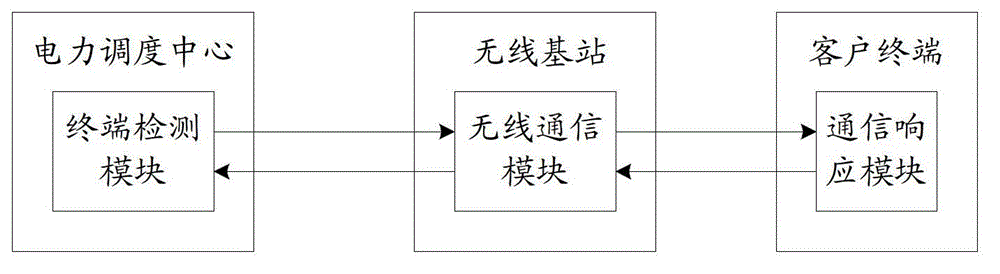
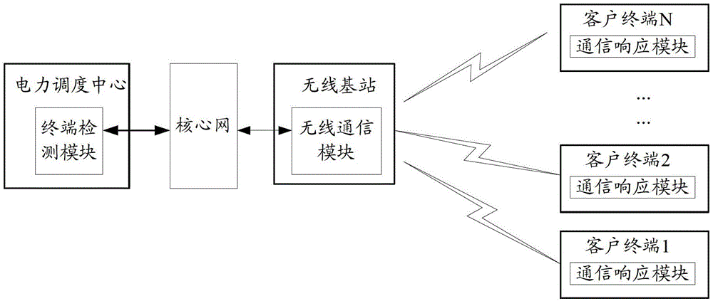
[0016] figure 1 It shows a schematic structural diagram of a client terminal equipment monitoring system of an electric power communication system in an embodiment, mainly including: a terminal detection module installed in the power dispatching center, a wireless communication module installed in a wireless base station, and a communication response module installed in a client terminal module.

[0017] Its working principle includes the following:

[0018] The terminal detection module sends the request data packet to the wireless communication module through the downlink; the wireless communication module sends the received request data packet to the communication response module in a wireless manner; the communication response module receives the r...


PUM


Abstract

The invention provides a system for monitoring customer terminal equipment of an electric power communication system. The system comprises a terminal detection module, a wireless communication module and a communication response module, wherein the terminal detection module is arranged in an electric power dispatching center; the wireless communication module is arranged in a wireless base station; the communication response module is arranged in a customer terminal; the terminal detection module transmits a request data packet to the wireless communication module through a downlink; the wireless communication module transmits the request data packet to the communication response module in a wireless way; the communication response module receives the request data packet and returns a confirmation data packet to the wireless communication module; and the wireless communication module transmits the confirmation data packet to the terminal detection module through an uplink. By the technology provided by the invention, network failure information can be timely acquired by the electric power dispatching center, and the safety, stability and reliability of electric power appliances can be ensured; and meanwhile, when a service interruption failure occurs, a failure reason can be rapidly confirmed by the system, and the efficiency of failure removal is improved.

Description

technical field [0001] The invention relates to the technical field of electric power communication, in particular to a monitoring system for client terminal equipment of the electric power communication system. Background technique [0002] In recent years, the research on the topic of smart grid has put forward higher requirements for the integration of information communication technology and grid technology. The smart grid has already covered distribution network automation and the integration of business and distribution. It takes the power system including power generation, transmission, distribution and power consumption as the object, and integrates power grid control technology, information communication technology and management technology together. Integrate together to realize the intelligent exchange of information in all links from power generation to power consumption, and systematically optimize power production, transmission and use. [0003] With the devel...

Claims


Application Information

Patent Timeline
Patent Type & Authority Applications(China)
IPC IPC(8): H04W24/04
Inventor 徐键陈宝仁杨俊权张国翊张斌满洋
Owner CHINA SOUTHERN POWER GRID COMPANY
Why Eureka
Try Eureka