A kind of voc tail gas water sealing device and water sealing method

A technology of water sealing device and exhaust gas, which is applied in the direction of valve device, valve heating/cooling device, valve details, etc., which can solve the problems of generating air bubbles, entraining liquid droplets, affecting the effect of condensate recovery, etc.

Active Publication Date: 2019-11-29
SINOPEC SHANGHAI ENG +1
View PDF10 Cites 0 Cited by
  • Summary
  • Abstract
  • Description
  • Claims
  • Application Information

AI Technical Summary

Problems solved by technology

[0004] The common method for airtight collection of VOC tail gas is VOC tail gas water sealing, but this method has many disadvantages: bubbles will be generated during the water sealing process; liquid droplets will be entrained when the exhaust gas is discharged; during the water sealing process, the temperature of the water sealing liquid will rise, Affect the recovery effect of condensate

Method used


Image

  • A kind of voc tail gas water sealing device and water sealing method
  • A kind of voc tail gas water sealing device and water sealing method

Examples


Embodiment 1

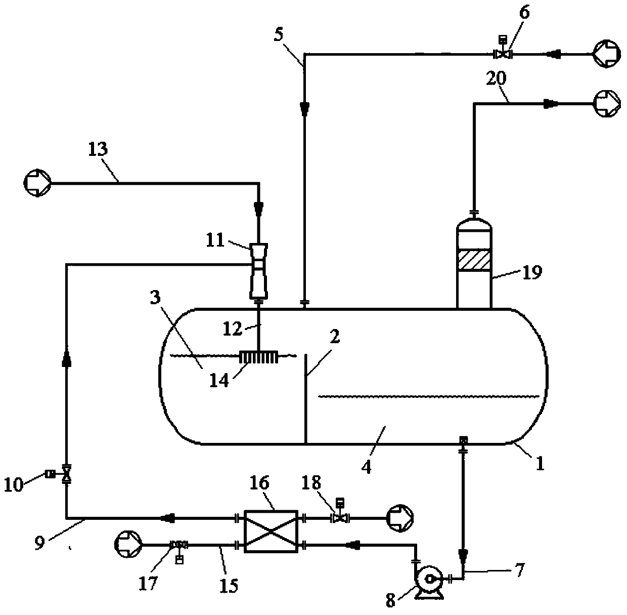
[0094] An exemplary embodiment of the present invention, such as figure 1 As shown, a VOC tail gas water sealing device includes a water sealing device, a backflow device, a cooling device, a water inlet device, an air intake device and an exhaust device.

[0095] The water sealing device includes a water sealing tank 1, a baffle 2 is arranged inside the water sealing tank 1, and the baffle 2 divides the water sealing tank 1 into a first chamber 3 and a second chamber 4, and the first chamber 3 and the second chamber The top of the chamber 4 communicates, but the bottoms of the first chamber 3 and the second chamber 4 do not communicate.

[0096] Further, the liquid level of the sealing liquid in the first chamber 3 is higher than the liquid level of the sealing liquid in the second chamber 4 .

[0097] The water inlet device includes a first water inlet pipe 5 , the first end of the first water inlet pipe 5 communicates with the water seal tank 2 , and the water seal liquid ...

Embodiment 2

[0125] This embodiment is a preferred embodiment of the present invention, and this embodiment is further optimized on the basis of Embodiment 1.

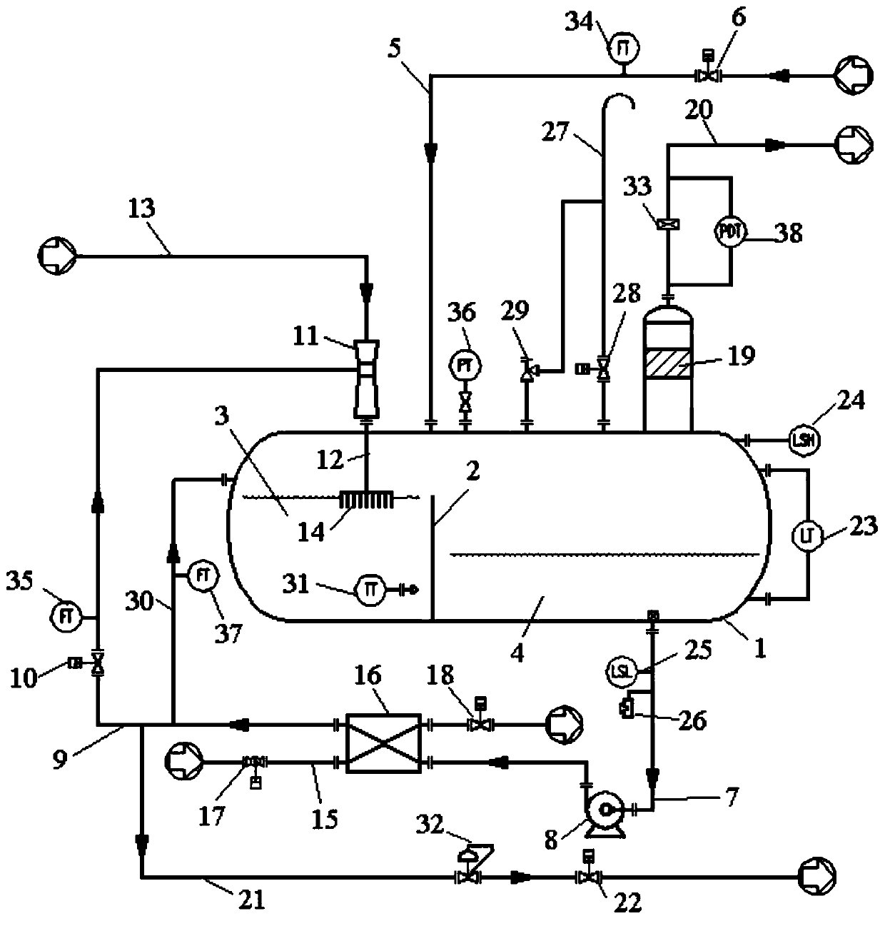
[0126] Such as figure 2 As shown, the VOC tail gas water sealing device of this embodiment, on the basis of Embodiment 1, further includes: a waste water discharge device, a liquid level control device, a pressure control device, a temperature control device, a fire protection device and multiple transmitters.

[0127] The first water inlet pipe 5 is provided with a second transmitter 34, the second transmitter 34 is located between the first valve 6 and the water seal tank 1, and is used to detect the flow rate of the first water inlet pipe 5 to the water seal tank 1. The flow rate of the sealing fluid, that is, the second transmitter 34 is a flow rate transmitter.

[0128] A third transmitter 35 is arranged on the circulation pipe 9, and the third transmitter 35 is located between the second valve 10 and the vacuum device 11, a...


PUM


Abstract

The invention relates to a VOC tail gas water sealing device. The VOC tail gas water sealing device comprises a water sealing tank, a first water inlet pipe, a first water outlet pipe, a circulating device, a circulating pipe, a vacuum device, an inserting pipe, a bubble breaking device, a cooling pipe, a foam removing device and a first exhaust pipe, wherein the cooling pipe and the circulating pipe achieve temperature exchange in a heat exchange device. The invention further relates to a VOC tail gas water sealing method. The VOC tail gas water sealing device has the advantages that the bubble breaking device is arranged, and therefore the condition that bubbles are generated in water sealing liquid when VOC tail gas enters the water sealing tank is avoided; the foam removing device is arranged, and therefore the condition that liquid drops are mixed in the VOC tail gas when the VOC tail gas is exhausted from the water sealing tank is avoided; in addition, circulation and heat exchange are conducted on the water sealing liquid, the water sealing liquid in the water sealing tank keeps constant, and the condensate recycling efficiency is improved; the water sealing device achievescontrol automation, and manual operation is reduced; and multiple transducers are arranged, the working states of all the units of the water sealing device can be obtained in real time, long-term goodrunning of the water sealing device is achieved through parameter setting, and the water sealing efficiency and safety are guaranteed.

Description

technical field [0001] The invention relates to the technical field of tail gas treatment, in particular to a VOC tail gas water sealing device and a water sealing method. Background technique [0002] With the increasingly stringent environmental protection requirements, the treatment of the three wastes (waste water, waste gas and solid waste), especially waste gas treatment, has attracted more and more attention. In the production of raw materials, a large amount of organic solvents will be used, so that a large amount of VOC tail gas will be discharged, such as reaction kettles, vacuum pumps and drying equipment. In this case, it is necessary to collect and treat the tail gas in production accordingly. [0003] At present, the commonly used VOC tail gas treatment scheme is as follows: firstly, the VOC tail gas is sealed and collected in each monomer workshop, and the condensate in the tail gas is recovered. According to the material properties and the exhaust gas treatm...

Claims


Application Information

Patent Timeline
Patent Type & Authority Patents(China)
IPC IPC(8): F16K13/10F16K37/00F16K49/00
Inventor 李振宇张超缪晡
Owner SINOPEC SHANGHAI ENG
Why Eureka
Try Eureka