A drilling fluid circulation manifold

A drilling fluid circulation and manifold technology, applied in the field of oil drilling, can solve the problems of different welding methods, low safety factor, large vibration, etc., and achieve the effects of reducing pressure loss, high bearing strength and high reliability

Active Publication Date: 2017-05-31
BC P INC CHINA NAT PETROLEUM CORP +1
View PDF6 Cites 0 Cited by
  • Summary
  • Abstract
  • Description
  • Claims
  • Application Information

AI Technical Summary

Problems solved by technology

At present, domestic thermal drilling fluid circulation manifold structures can be roughly divided into two types: the first type is the drilling fluid circulation manifolds for old drilling rigs produced many years ago. It meets the standard of convenience and quickness, but most of them are manufactured by welding drill pipe or oil rod, which has low safety factor, insufficient local strength and poor pressure resistance
The second type is that in recent years, although most of the drilling fluid circulation manifolds for new drilling rigs are produced according to the standard, and the pressure bearing capacity is guaranteed, the design is often not humane enough, and there are problems such as inconvenient use and large vibration. Manufacturers have different welding methods, which also cause uneven quality of drilling fluid circulation manifolds

Method used


Image

  • A drilling fluid circulation manifold
  • A drilling fluid circulation manifold

Examples


Embodiment Construction

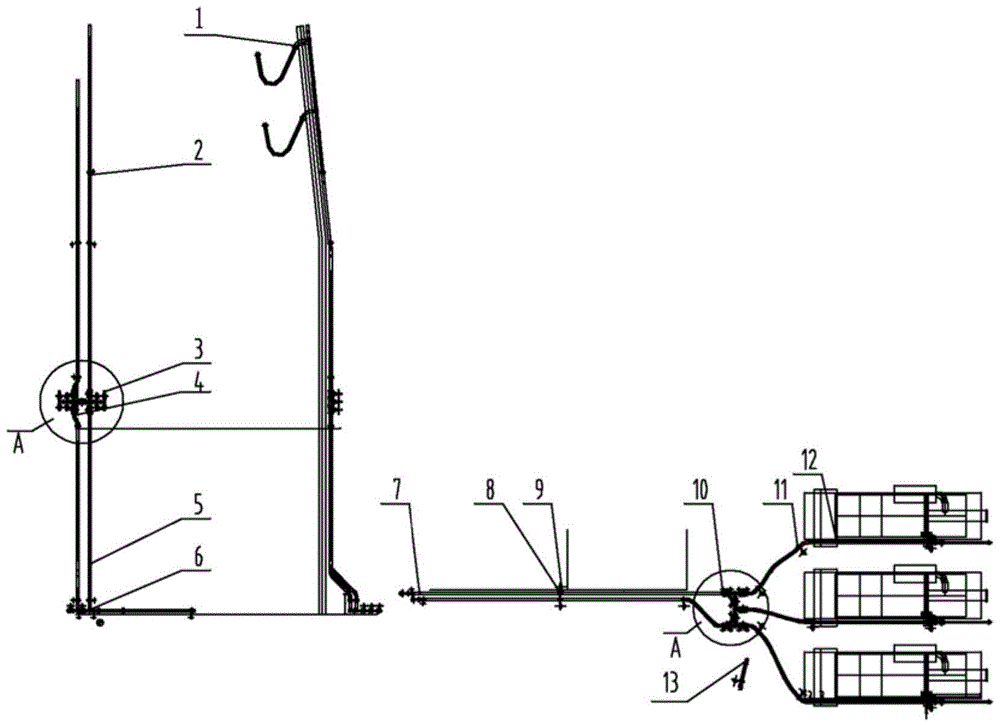
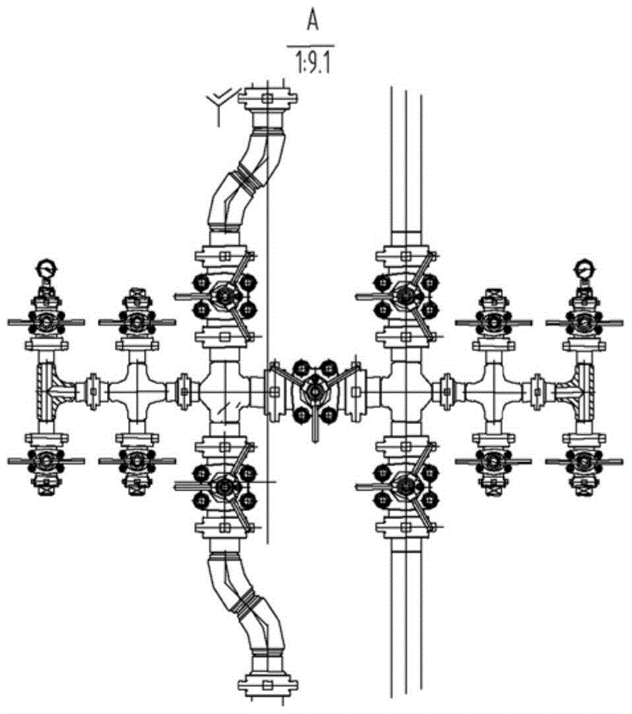
[0020] Attached below Figure 1-2 The drilling fluid circulation manifold structure of the present invention is described in detail.

[0021] A drilling fluid circulation manifold, which includes a gooseneck 1, a drill floor valve group 3, a drill floor valve group support 4, a standpipe 5, a drilling rig base clamp 7, a union 8, and a safety chain 9. The ground valve group 10, the mud pump pipe clamp 12, the automatic grouting control system and the pump pipeline; the gooseneck 1 has a rib plate, and there are hoisting holes on the rib plate, and the lengths of the two goosenecks are equal. Equipped with an extension nipple 2; the extension nipple 2 is connected to the riser 5; a drill floor valve group 3 is also arranged between the extension nipple 2 and the riser 5, and the drill floor The valve group 3 is arranged on the drill floor valve group bracket 4; the drill floor valve group 3 includes several three-way and four-way connections, and the three-way and four-way con...


PUM


Abstract

The invention relates to a drilling fluid circulating manifold. The drilling fluid circulating manifold comprises a gooseneck pipe, a drill floor valve bank, a drill floor valve bank support, a stand pipe, a drilling machine base pipe clamp, a union, a safe chain, a ground valve bank, a slurry pump pipe clamp, an automatic grouting control system and a pump penetrating pipeline, wherein the drill floor valve bank is arranged on the drill floor valve bank support; the drill floor valve bank support is provided with a support height adjusting device; the safe chain comprises a three-hole pipe clamp, a shackle and a steel chain; the automatic grouting control system comprises a control main engine, a control module and a display module; the control main engine is connected with a slurry pump and a grouting pump through the control module; and the control module comprises a main power module, a standby power module, a CPU (central processing unit) master control module, a CPU standby control module, a communication interface and an acquiring module. The drilling fluid circulating manifold has the advantages that the structure is simple, the design is reasonable, the drilling fluid circulating manifold is convenient to use and is safe and durable, cost of equipment and labor intensity are reduced, and drilling efficiency is greatly improved.

Description

technical field [0001] The invention relates to the technical field of petroleum drilling, in particular to a drilling fluid circulation manifold. Background technique [0002] Drilling fluid manifold is the necessary equipment to increase the drilling speed in Gaoya jet drilling. It collects the mud discharged from the mud pump, and with the help of the control of the high-pressure valve group, the high-pressure mud liquid is input into the inner cavity of the drill pipe and ejected from the drill bit to generate high-pressure mud. Torrent, high pressure jet drilling is realized, the drilling speed is greatly improved, and the drilling cost is reduced. At present, domestic thermal drilling fluid circulation manifold structures can be roughly divided into two types: the first type is the drilling fluid circulation manifolds for old drilling rigs produced many years ago. It meets the standard of convenience and quickness, but most of them are manufactured by welding drill pi...

Claims


Application Information

Patent Timeline
Patent Type & Authority Patents(China)
IPC IPC(8): E21B21/00E21B21/08
Inventor 王臣聂永坤李志刚周小刚马永恒
Owner BC P INC CHINA NAT PETROLEUM CORP
Why Eureka
Try Eureka