Control circuit for atomizers and method thereof

A technology for controlling circuits and control methods, which is applied in therapeutic nebulizers, general control systems, program control, etc., and can solve the problems of not being fresh enough, inconvenient, and unable to reach the liquid evenly.

Active Publication Date: 2012-10-17
JOYETECH EURO HLDG
View PDF3 Cites 33 Cited by
  • Summary
  • Abstract
  • Description
  • Claims
  • Application Information

AI Technical Summary

Problems solved by technology

This atomization solution is somewhat similar to the common ultrasonic heater in the home, but the ultrasonic atomizer has the problems of small atomization volume and insufficient energy utilization
[0005] Some existing atomizers currently on the market have the following problems: first, the liquid medicine is injected into the filling layer in the nozzle cavity, so it can be seen that the liquid medicine is not fresh enough, and the storage capacity of the liquid medicine is small. After finishing, the user must drop the liquid medicine into the nebulizer before continuing to use it. In this way, if the user wants to use beauty products outdoors or at work, he has to bring a bottle of li

Method used

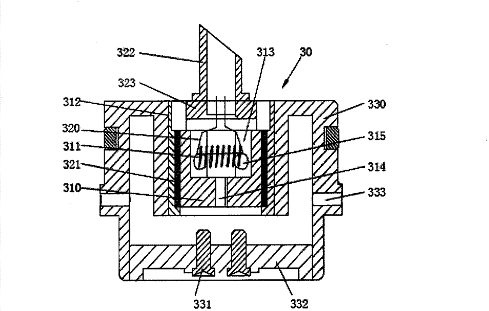
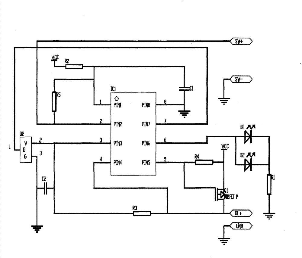

Image

  • Control circuit for atomizers and method thereof
  • Control circuit for atomizers and method thereof
  • Control circuit for atomizers and method thereof

Examples


Embodiment approach 1

[0044] Include the following steps:

[0045] Step 1, initialize the system: the microcontroller sets the time when the circuit enters the lock, and sets the time when the circuit is unlocked;

[0046] Step 2, the single-chip microcomputer detects the signal from the key switch output: the single-chip microcomputer in the locked state receives 5 switching signals from the key switch within 1.5 seconds, and the single-chip microcomputer unlocks. Since both locking and unlocking are to turn on the key switch 5 times within 1.5 seconds, if the user makes the switch turn on once or twice due to misoperation, the microcontroller will not be unlocked. And because the time is short, there will be no such situation that the key switch is turned on 5 times within 1.5 seconds due to misoperation, so this setting is safer.

[0047] After unlocking, the single-chip microcomputer receives the signal from the key switch again, and the circuit is connected to the single-chip microcomputer to...

Embodiment approach 2

[0061] This implementation mode is completely the same as the above implementation mode except that the unlocking circuit lock and the locking circuit are different from the above one implementation mode.

[0062] The single-chip microcomputer detects the signal from the key switch output: the single-chip microcomputer in the locked state receives the first continuous signal from the key switch output in 4 seconds, and the single-chip microcomputer is unlocked. After unlocking, the single-chip microcomputer receives the signal from the key switch again, and the circuit Turn on the microcontroller to output electrical signals to the transistor. The transistor amplifies the signal from the microcontroller and outputs it to the load. If the MCU receives the second continuous signal from the key switch output in 8 seconds, the MCU enters the locked state and has no output signal; that is, press and hold the key switch for 8 seconds to continuously output the signal of the switch c...


PUM


Abstract

The invention discloses a control circuit for atomizers, and the control circuit comprises a key switch, a single chip and a transistor, wherein the key switch is used for sending a switch signal which is used for connecting or disconnecting the control circuit; the single chip is connected with the key switch and has a locking function; after receiving the signal from the key switch, the single chip enters into a self locking state without an output signal or is unlocked; and the transistor is connected with an output end of the single chip and has a signal amplification function. Through the control circuit for atomizers, misoperation can be avoided to ensure that the key switch is connected.

Description

[0001] The patent application for the present invention is a divisional application. The application number of the original application is 201010527480.9, the application date is November 1, 2010, and the name of the invention is: oral suction portable atomizer. technical field [0002] The invention relates to an atomizing device for electronic cigarettes, in particular to a control circuit and method for the atomizer. Background technique [0003] Now people's lives and social activities are strengthened, and the communication between people is becoming more and more important, and many people are confused by problems such as bad breath. Although there are also items such as chewing gum and throat lozenges that can solve temporary needs, but Its waste produces new environmental pollution thereupon, as eaten chewing gum, packing tin plate etc. [0004] In the early days, it was proposed to heat the medicinal liquid through a mechanical device for the user to use. Although ...

Claims


Application Information

Patent Timeline
IPC IPC(8): A61M11/04G05B19/042
Inventor 邱伟华
Owner JOYETECH EURO HLDG
Why Eureka
Try Eureka