Method for setting load distribution of finish rolling band steel

A load distribution and setting method technology, applied in metal rolling, metal rolling, rolling mill control devices, etc., can solve the problems of low adjustment efficiency, insurmountability, and poor coordination between stands

Active Publication Date: 2012-10-17
BAOSHAN IRON & STEEL CO LTD
View PDF4 Cites 35 Cited by
  • Summary
  • Abstract
  • Description
  • Claims
  • Application Information

AI Technical Summary

Problems solved by technology

Its limitations are: ① only adjust the distribution of two racks each time, the coordination between the racks is not good, and the adjustment efficiency is low; Distribution, cannot overcome the disadvantages of rolling force distribution

Method used


Image

  • Method for setting load distribution of finish rolling band steel
  • Method for setting load distribution of finish rolling band steel
  • Method for setting load distribution of finish rolling band steel

Examples


Embodiment 1

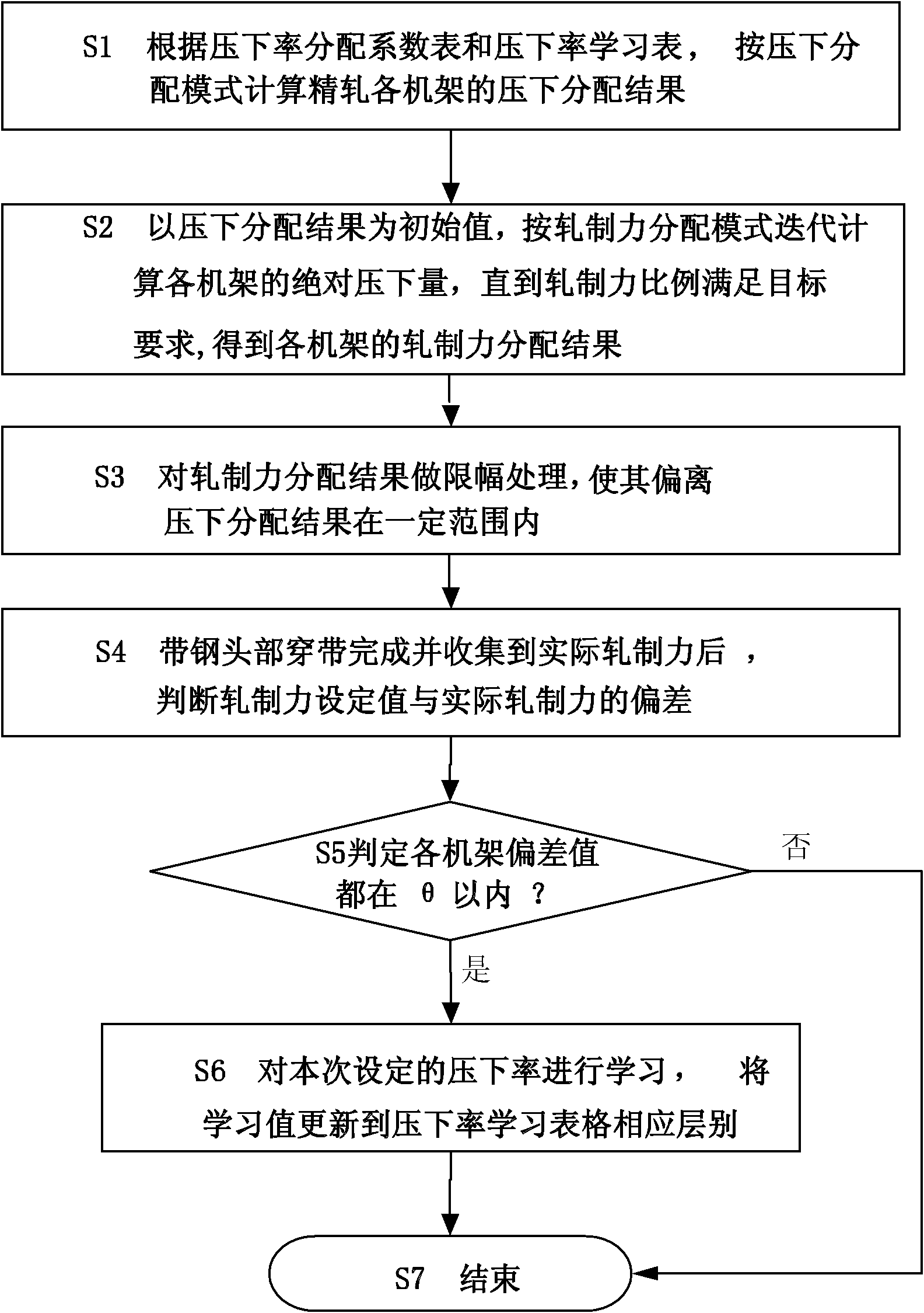
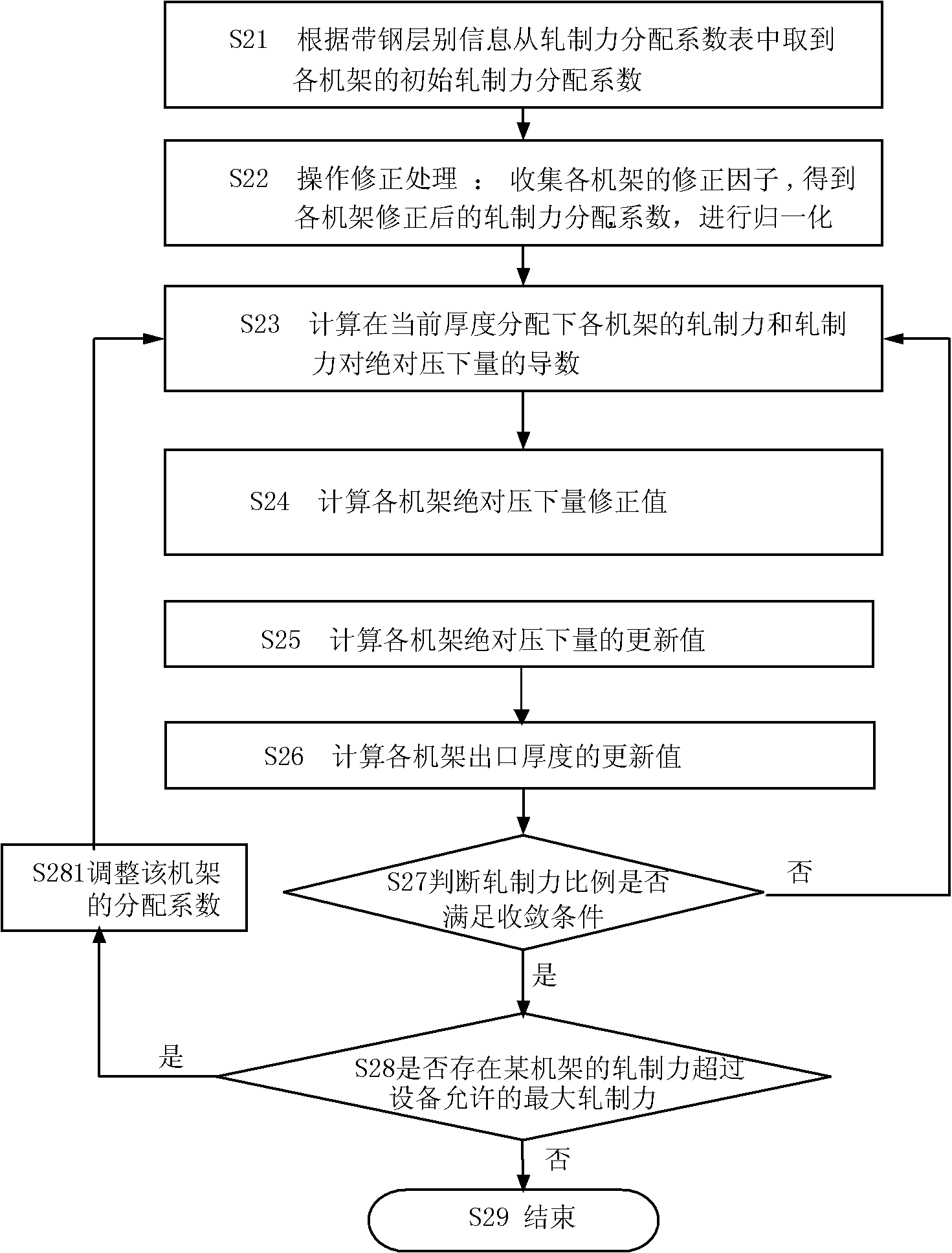
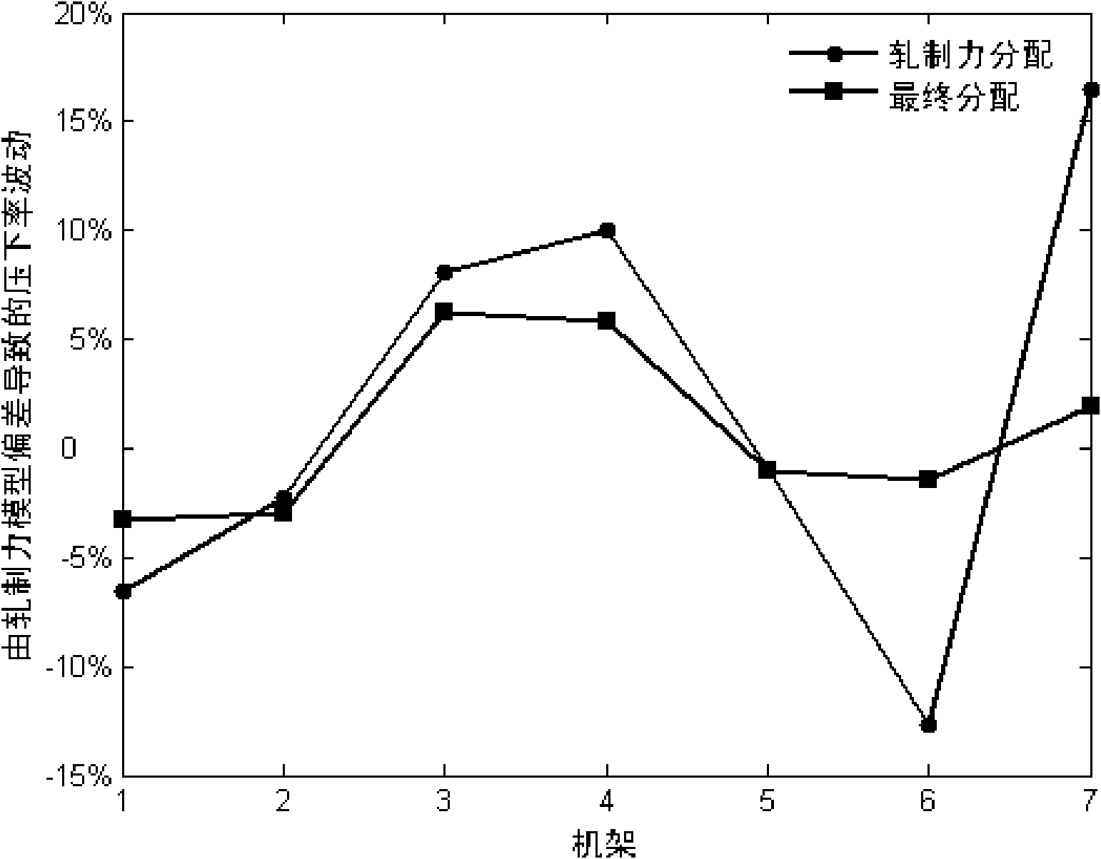
[0180] Focus on explaining the entire calculation process. The final result is the distribution of rolling force after reduction distribution and limiting, which overcomes the disadvantages of large fluctuations in stand reduction rate when rolling force distribution is used alone (in this case, when the error of the rolling force model is large and the process conditions change greatly occurs, the rolling force distribution needs to adjust the reduction rate to meet the requirements of the rolling force ratio of each stand, so the reduction rate fluctuates greatly; when the reduction distribution is used, the reduction rate of each stand remains almost unchanged), It is beneficial to improve the setting accuracy and rolling stability of the rolling schedule of the finished strip steel.

[0181] The information of a certain strip is as follows: the thickness of the intermediate billet is 40.69mm, the thickness of the final rolling is 2.0mm, the width of the strip is 1233.6mm, ...

Embodiment 2

[0225] Rack equipment limit testing.

[0226] Strip steel information: the thickness of the intermediate billet is 42.308mm, the thickness of the final rolling is 4.597mm, and the number of passes is n=7. The rolling force distribution coefficient required in step S2 is as follows in Table 15:

[0227] SGF

THICK

α1

α2

α3

α4

α5

α6

α7

11002

16

1

0.98

0.88

0.78

0.62

0.45

0.36

[0228] Rolling force overrun inspection

[0229] For the convenience of comparison, the load distribution in two cases is calculated separately: one is that there is no limit to the maximum rolling force of F2; the other is that the maximum rolling force of F2 is limited, assuming The calculation results are compared in Table 16 below.

[0230]

F1

F2

F3

F4

F5

F6

F7

α i

1

0.98

0.88

0.78

0.62

...


PUM


Abstract

The invention relates to a method for setting the load distribution of finish rolling band steel, belonging to the field of production control of finish rolling band steel, and solving the problems that the rolling force proportion of stands is large in fluctuation when the rolling condition is changed under the pressed-down distribution mode, and the thickness distribution of the stands is large in fluctuation when the rolling force model is large in deviation under the rolling force distribution mode. According to the invention, the pressed-down distribution mode and the rolling force distribution mode are combined; the rolling force distribution result is restricted by the distribution range determined by pressed-down distribution; the requirement that the rolling force of stands is decreased according to proportion is met while the thickness distribution fluctuation of the stands is reduced; the results of two distribution modes are gradually consistent, and the iterations are gradually reduced by learning a pressed-down rate learning table when the deviation of the rolling force model is small; and the fluctuation range of the pressed-down rate of the stands is effectively controlled through the pressed-down distribution amplitude limit when the deviation of the rolling force model is large. By adopting the method, the advantages of the two modes are combined and the shortages are overcome, so that the rolling schedule setting precision and the rolling stability of the finish rolling band steel are effectively improved.

Description

technical field [0001] The invention relates to the field of production control of finish-rolled strip steel, in particular to a method for setting load distribution of finish-rolled strip steel. Background technique [0002] In hot strip rolling mills, the formulation of rolling regulations plays an important role in improving product quality. Whether it is reasonable or not has a great impact on the quality of products, the difficulty of adjusting rolling equipment, the reliability of unit operation and the production process. have a direct impact on the stability of the Rolling regulations generally include reduction system, speed system, tension system, temperature system, etc. The reduction system refers to the distribution system of the reduction amount of each frame (or each pass), which is usually called load distribution or thickness distribution in the industry. [0003] Load distribution is the core of the rolling procedure, which directly affects product qualit...

Claims


Application Information

Patent Timeline
Patent Type & Authority Applications(China)
IPC IPC(8): B21B37/16B21B37/58
Inventor 李维刚张健民单旭沂董晖
Owner BAOSHAN IRON & STEEL CO LTD
Why Eureka
Try Eureka