Soldering clamping device for engine oil cooler
A technology of oil cooler and clamping device, which is applied in the direction of auxiliary devices, welding equipment, metal processing equipment, etc., can solve the problem that the vertical accuracy and assembly accuracy of multi-layer chips cannot be guaranteed, and the installation position accuracy of small flange mounting holes cannot be guaranteed. Problems such as flange clamping accuracy cannot be guaranteed, so as to achieve the effects of not being easily twisted, ensuring overall verticality, and improving clamping efficiency
- Summary
- Abstract
- Description
- Claims
- Application Information
AI Technical Summary
Problems solved by technology
Method used
Image

Examples
Embodiment Construction
[0021] The present invention will be further described below in conjunction with the accompanying drawings and specific embodiments.
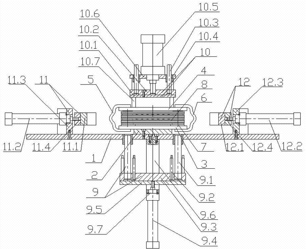
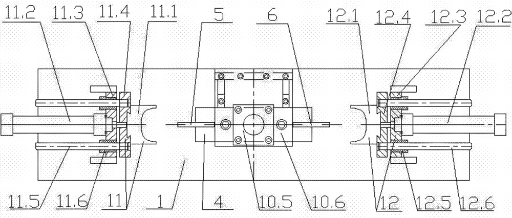
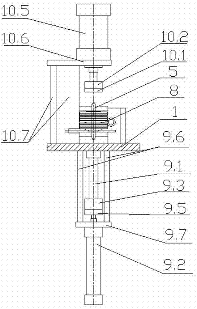
[0022] see figure 1 , figure 2 , image 3 , Figure 4 and Figure 5 As shown, the oil cooler brazing and clamping device of the present invention includes a fixed plate 1, a bottom plate 2, a left clamping mechanism 5, a right clamping mechanism 6, a lower brazing plate 3 for placing the oil cooler, and a lower brazing plate for placing the oil cooler. The upper brazing plate 4, the bottom plate 2 is fixed on the fixed plate 1, the lower brazing plate 3 is placed on the bottom plate 2, the left clamping mechanism 5 and the right clamping mechanism 6 are clamped on the On the lower brazing plate 3 and the upper brazing plate 4 of the oil cooler, it also includes a positioning mechanism 9, a pressing mechanism 10, and a left camming mechanism 11 and a right camming mechanism 12 matching the shape of the end of the oil cooler. The positionin...
PUM
 Abstract
Description
Claims
Application Information