
Stacking robot gripper

A stacking robot and rear side plate technology, applied in the field of robots, can solve the problems of large space occupation, complex motion mechanism, unstable cargo clamping, etc., achieve stable grasping of cargo, simple structure of the gripper, and increase the scope of use Effect

Active Publication Date: 2012-10-17
扬州牧羊唯美自动化控制有限公司
View PDF6 Cites 40 Cited by
  • Summary
  • Abstract
  • Description
  • Claims
  • Application Information

AI Technical Summary

Problems solved by technology

[0005] However, the movement mechanism of the gripper of the above-mentioned palletizing robot is complex, takes up a large space, is bulky overall, inflexible in operation, inconvenient in maintenance, slow in grabbing speed, low in production efficiency, and grabs large or small bags. At this time, the clamping of the goods is unstable, and there are potential safety hazards in the stacking process

Method used


Image

  • Stacking robot gripper
  • Stacking robot gripper
  • Stacking robot gripper

Examples


Embodiment Construction

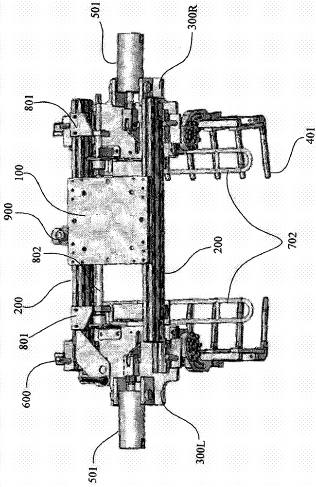
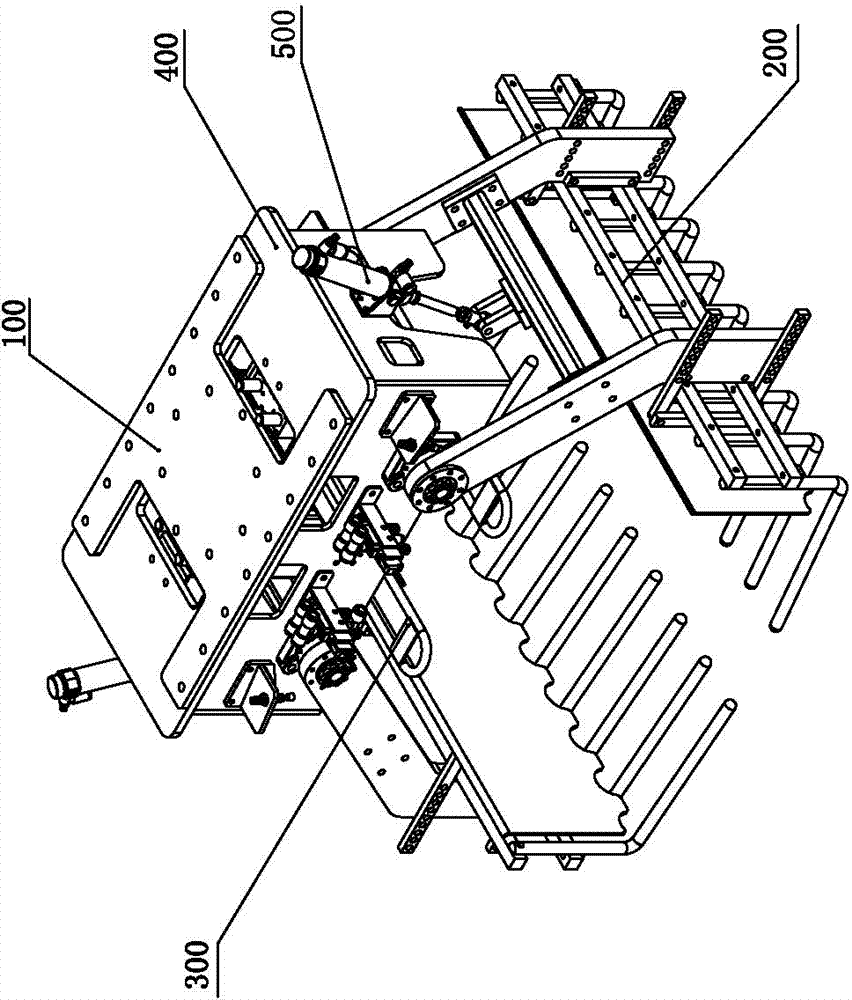
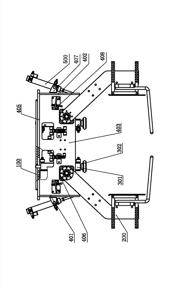
[0022] Such as figure 2 — Figure 5 Shown is the gripper of the palletizing robot of the present invention, comprising a main frame mechanism 400 mainly composed of a front side plate 403, a rear side plate 404, a left side plate 401, a right side plate 402 and a top plate 405; The connecting plate 100, the connecting plate 100 is used to connect the gripper with the main body of the palletizing robot; the left and right sides of the front side plate 403 and the rear side plate 404 are supported with a rotatable gripping tooth mechanism 200; The left and right sides of the main frame mechanism 400 are used to drive the light-duty cylinder 500 to rotate the tooth-grabbing mechanism 200. The light-duty cylinder 500 is respectively fixed on the outside of the left side plate 401 and the right side plate 402. Above, the main frame mechanism 400 is provided with a solenoid valve and a pressure reducing valve for controlling the action of the light cylinder. Such as image 3 As...


PUM


Abstract

The invention relates to a stacking robot gripper in the field of robots for stacking during package and transportation. The stacking robot gripper comprises a main frame mechanism, a connecting plate and two groups of symmetrical tooth gripping mechanisms and also comprises light-type cylinders, wherein the main frame mechanism mainly comprises a front side plate, a rear side plate, a left side plate, a right side plate and a top plate; the connecting plate is fixed on the top plate; the tooth gripping mechanisms are rotatably supported at the front side plate and the lower side plate of the main frame mechanism; the light-type cylinders are symmetrically and obliquely arranged at the left side and the right side of the main frame mechanism and are used for driving the tooth gripping mechanisms to rotate; each group of tooth gripping mechanisms comprise a plurality of L-shaped gripping teeth which are fixedly connected by a plurality of connecting rods, are uniformly distributed and point to the same side; the gripping teeth are fixedly connected with two rows of parallel rotating arms by the connecting rods; rotating shafts are connected at the end parts of the two rotating arms; the front side plate and the rear side plate are correspondingly provided with mounted bearings for supporting and installing the rotating shafts; and the corresponding inner sides of the two groups of tooth gripping mechanisms are also provided with pressing plates with adjustable distance, and the pressing plates are used for clamping the two sides of a gripped object. The stacking robot gripper has the advantages of simple and compact structure, flexible operation, fast gripping speed, stable gripping and wide application range.

Description

technical field [0001] The invention relates to a machine for handling and palletizing bags or boxes, in particular to a palletizing robot gripper, which belongs to the field of robots. Background technique [0002] At present, the handling and palletizing methods used in my country's palletizing operations are: one is manual handling; the other is mechanical palletizing machines; the third is palletizing robots. Manual handling has the problems of high labor intensity, low efficiency, and poor safety; while mechanical palletizers are limited by factors such as structure, there are large footprints, troublesome operation procedures (some even cannot be changed), power consumption, etc. Big and other shortcomings. Palletizing robots are suitable for goods packed in various shapes such as cartons and bags, and have reliable performance and simple maintenance. In order to improve production efficiency, save costs, and create benefits, enterprises are increasingly applying ...

Claims


Application Information

Patent Timeline
Patent Type & Authority Applications(China)
IPC IPC(8): B25J9/00B25J15/00
Inventor 董紫洁左恩海周文明
Owner 扬州牧羊唯美自动化控制有限公司
Learn More