Robot
A technology of robots and working axes, which is applied in the field of robots and can solve problems such as high cost
- Summary
- Abstract
- Description
- Claims
- Application Information
AI Technical Summary
Problems solved by technology
Method used
Image

Examples
no. 1 approach
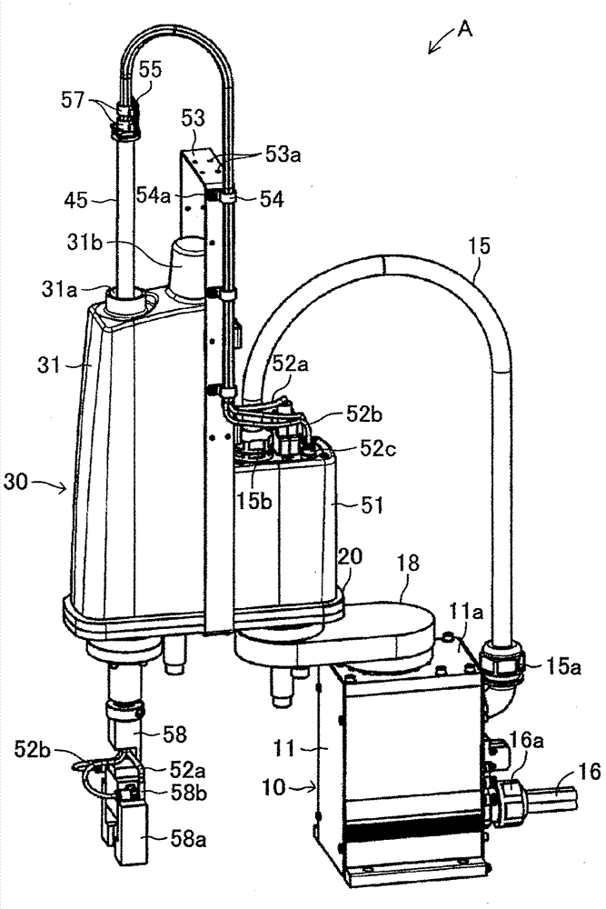
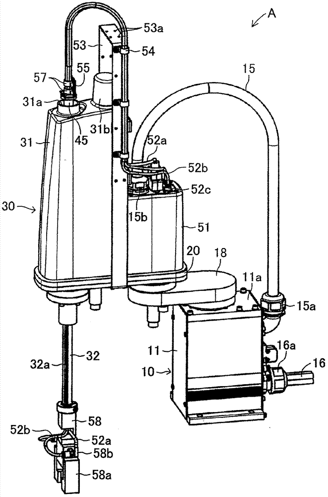
[0029] Figure 1 to Figure 3 A SCARA-type robot (planar articulated robot) A which is a robot according to the first embodiment of the present invention is shown. The SCARA robot A includes a base portion 10 , a first arm 18 , a second arm 20 , and an elevating and rotating drive device 30 provided on the second arm 20 .
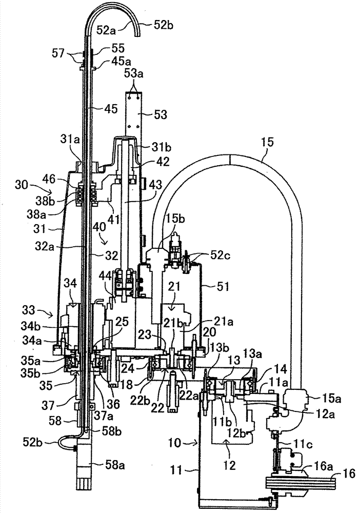
[0030] The base part 10 is fixedly installed on a floor or a table or the like. Such as image 3 As shown, the base part 10 includes: a rectangular box-shaped housing 11; a motor 12 fixedly arranged on the upper part of the housing 11; and an upper surface part 11a assembled on the upper part of the motor 12 and fixedly arranged on the housing 11 The reducer 13. In addition, in this specification, the front-back direction refers to the image 3 The direction perpendicular to the paper surface (the front side is the front direction), in the following description, the up-down direction and left-right direction are based on image 3 set up.
[0031] An at...
no. 2 approach
[0060] Figure 7 and Figure 8 A SCARA-type robot B according to a second embodiment of the present invention is shown. The main difference between the structure of the SCARA robot B and the structure of the SCARA robot A is that instead of the vertical rotation drive device 30 in the SCARA robot A, a vertical rotation drive device 60 having the following structure is provided.
[0061] Lifting rotary driving device 60 comprises cover 61, hollow working shaft 71, working shaft assembly 70 (referring to Figure 9 ), the rotating device 62 for rotating the working shaft assembly 70 around the axis, and the lifting device 65 for moving the working shaft assembly 70 in the vertical direction. Furthermore, a hollow shaft 68 is detachably connected to the upper end portion of the operating shaft assembly 70 . The cover 61 has a box-like shape having two different heights as the covers 31 and 51 of the SCARA robot A are integrally formed, and does not have a portion corresponding ...
no. 3 approach
[0072] Figure 14 to Figure 18 A SCARA-type robot C according to a third embodiment of the present invention is shown. The structure of the SCARA robot C differs from that of the SCARA robot B in that it has a vertical rotation drive device having the following structure instead of the vertical rotation drive device 60 in the SCARA robot B of the second embodiment.
[0073] Figure 14 to Figure 16 Indicates the connecting portion of the working shaft assembly 80 and the hollow shaft 85, Figure 17 and Figure 18 A connection portion between the working shaft assembly 80 and the manipulator 88 side is shown. The operation shaft assembly 80 has a structure in which connection members 82 and 83 are attached to the upper and lower openings of the hollow operation shaft 81 , respectively, and the connection members 82 and 83 are connected by connection wires 84 a. The operating shaft 81 is constituted by a steel ball spline shaft in which a plurality of vertical grooves 81 a ar...
PUM
 Abstract
Description
Claims
Application Information