Tension rod structure of injection molding machine

A tie rod structure and technology of injection molding machine, applied in the field of tie rod assembly of injection molding machine clamping mechanism, can solve the problems of broken threaded end of tie rod and short service life, and achieve the effect of prolonging service life, small volume and compact structure

Active Publication Date: 2012-10-17
NINGBO HAIXING MACHINERY MFG
View PDF1 Cites 8 Cited by
  • Summary
  • Abstract
  • Description
  • Claims
  • Application Information

AI Technical Summary

Problems solved by technology

By providing the large-pitch zigzag tie rod structure technology, it solves the problems that the tie rod is easy to break at the thread end and has a short service life.

Method used


Image

  • Tension rod structure of injection molding machine

Examples


Embodiment Construction

[0026] Embodiments of the present invention will be further described in detail below in conjunction with the accompanying drawings.

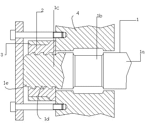
[0027] The serial numbers and names of the above drawings are: tie rod 1, smooth section 1a of tie rod, stress groove 1b, mold adjusting thread section 1c, large pitch tooth body 1d, head end 1e of mold adjusting thread section, tie rod mold adjusting nut 2, outer ring 3 .

[0028] as attached figure 1 As shown, a tie rod structure of an injection molding machine according to the present invention includes a tie rod 1 and a tie rod mold adjusting nut 2. The tie rod 1 includes a mold adjusting threaded section 1c, wherein a large mold is formed on the mold adjusting threaded section 1c. Pitch tooth body 1d, the pull rod mold adjusting nut 2 is screwed with the mold adjusting thread section 1c through the large pitch tooth body 1d, and a large fillet transition is used at the step or the undercut.

[0029] In the embodiment, the pitch of the la...


PUM

PropertyMeasurementUnit
Pitchaaaaaaaaaa
Diameteraaaaaaaaaa
Diameteraaaaaaaaaa

Abstract

The invention relates to a tension rod structure of an injection molding machine in the field of injection molding machines. Aiming at the defect of the breakage and failure of the tension rod of the conventional injection molding machine, the tension rod structure is designed. The tension rod structure comprises a tension rod and a tension rod mold adjusting nut, wherein the tension rod comprises a mold adjusting thread section; a coarse pitch tooth body is formed on the mold adjusting thread section; and the tension rod mold adjusting nut is in screw-thread fit with the mold adjusting thread section by the coarse pitch tooth body and is subjected to transition by using a large round corner at a step or a tool retracting groove. According to the design key point, a thread tooth body of the mold adjusting thread section is coarse pitch sawteeth; the outer diameter of a mold adjusting thread section body is slightly greater than that of a stress groove; the mold adjusting thread section body is in a cylindrical shape; an outer ring is matched outside the tension rod mold adjusting nut; and a mold adjusting screw cap is held tightly by the outer ring. By the improvement of the structure, the aims of running a mold closing mechanism reliably and prolonging the service life of the tension rod are fulfilled. The tension rod structure is simple and convenient to machine, and the technical content of the injection molding machine is improved.

Description

technical field [0001] The invention relates to the technical field of a tie rod assembly of a clamping mechanism of an injection molding machine, in particular to a tie rod structure of an injection molding machine. Background technique [0002] The tie rod is a high-rigidity elastic part that generates the clamping force of the mold clamping mechanism of the injection molding machine, which is directly related to the reliable operation and service life of the mold clamping mechanism. The mold-adjusting thread of the pull rod of the existing mold clamping mechanism is generally an ordinary coarse thread. When the injection molding machine is used under full load, high tension, long time, and high frequency, due to the poor fatigue resistance of the ordinary coarse thread, it is easy to break the thread. broken. [0003] An existing hybrid-driven mold clamping mechanism for an all-electric injection molding machine includes a mold adjusting nut, a support plate, a tie rod, ...

Claims


Application Information

Patent Timeline
IPC IPC(8): B29C45/66
Inventor 陈兴良
Owner NINGBO HAIXING MACHINERY MFG
Why Eureka
Try Eureka