Hydraulically driven engineering machine chassis and engineering machine

A technology of construction machinery and driving mechanism, applied in the power system and hydraulic field, can solve the problems of large chassis space, complex driving environment, affecting the layout of other components, etc., to achieve the effect of large driving force, simplified chassis structure, and optimized layout

Inactive Publication Date: 2012-10-17
SANY HEAVY IND CO LTD (CN)
View PDF5 Cites 2 Cited by
  • Summary
  • Abstract
  • Description
  • Claims
  • Application Information

AI Technical Summary

Problems solved by technology

However, since the chassis of engineering vehicles needs to arrange the engine, fuel tank, hydraulic system, support device, operating parts, etc. that belong to the operation attribute, and the driving environm

Method used


Image

  • Hydraulically driven engineering machine chassis and engineering machine
  • Hydraulically driven engineering machine chassis and engineering machine
  • Hydraulically driven engineering machine chassis and engineering machine

Examples


Embodiment Construction

[0027] In order to understand the above-mentioned purpose, features and advantages of the present invention more clearly, the present invention will be further described in detail below in conjunction with the accompanying drawings and specific embodiments. It should be noted that, in the case of no conflict, the embodiments of the present application and the features in the embodiments can be combined with each other.

[0028] In the following description, many specific details are set forth in order to fully understand the present invention. However, the present invention can also be implemented in other ways different from those described here. Therefore, the protection scope of the present invention is not limited by the specific details disclosed below. EXAMPLE LIMITATIONS.

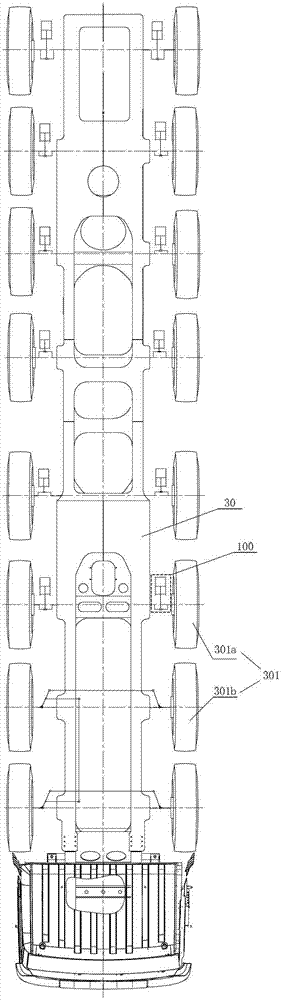
[0029] figure 1 It is a structural schematic diagram of an engineering machinery chassis according to an embodiment of the present invention. Such as figure 1 As shown, the construction machinery ...


PUM


Abstract

The invention provides a hydraulically driven engineering machine chassis, which comprises at least one hydraulic driving mechanism used for driving at least one wheel on the chassis. Each hydraulic driving mechanism comprises a hydraulic oil cylinder and a crankshaft, wherein each crankshaft comprises a main journal and a rod journal; the crankshafts are rotatablely arranged on the chassis through the main journals; the hydraulic oil cylinders are arranged on the chassis in a swing manner; a piston rod of each hydraulic oil cylinder is connected with the rod journals; the crankshafts can be driven to rotate by the hydraulic oil cylinders; the crankshafts are connected to the wheels; and the wheels can be driven to rotate by the hydraulic oil cylinders through the crankshafts. Correspondingly, the invention also provides an engineering machine. Through the technical scheme provided by the invention, the chassis structure of the engineering machine can be simplified, the chassis layout is optimized, and the requirement of low-speed and high-torsion working condition is met.

Description

technical field [0001] The invention relates to the field of power system and hydraulic technology, in particular, to a hydraulically driven engineering machinery chassis and an engineering machinery. Background technique [0002] With the development of construction machinery, on-board construction machinery such as ultra-long boom concrete pump trucks, truck cranes, and high-altitude fire trucks require a large number of special chassis for engineering vehicles. [0003] Most of the current construction machinery chassis use the drive shaft to drive the differential to drive the axle to run; there are also hydraulic motors or electric motors to drive the wheel reducer. However, since the chassis of engineering vehicles needs to arrange the engine, fuel tank, hydraulic system, support device, operating parts, etc. that belong to the operation attribute, and the driving environment is relatively complex, there are high requirements for the chassis passability and turning rad...

Claims


Application Information

Patent Timeline
IPC IPC(8): B60K17/10B60K23/02B62D5/06
Inventor 易小刚李东张作良
Owner SANY HEAVY IND CO LTD (CN)
Why Eureka
Try Eureka