Fixing clamping bolt device for steelmaking vacuum groove

A technology for fixing clips and vacuum grooves, applied in the field of fixed clip devices, can solve the problems of inconvenient maintenance and disassembly, failure to meet sealing requirements, difficult maintenance and other problems, and achieve easy replacement, reliable clamping force balance, and convenient disassembly. Effect

Inactive Publication Date: 2012-10-17
江苏三嘉矿冶设备有限公司
View PDF0 Cites 0 Cited by
  • Summary
  • Abstract
  • Description
  • Claims
  • Application Information

AI Technical Summary

Problems solved by technology

[0002] The original vacuum tank clamping device adopts conventional bolt connection and clamping, and the vacuum tank adopts conventional bolt connection clamping. The disadvantages are: 1. It is easy to deform, which cannot meet the sealing requirements and affects normal work; 2. Inconvenient maintenance and disassembly, difficult maintenance

Method used


Image

  • Fixing clamping bolt device for steelmaking vacuum groove

Examples


Embodiment Construction

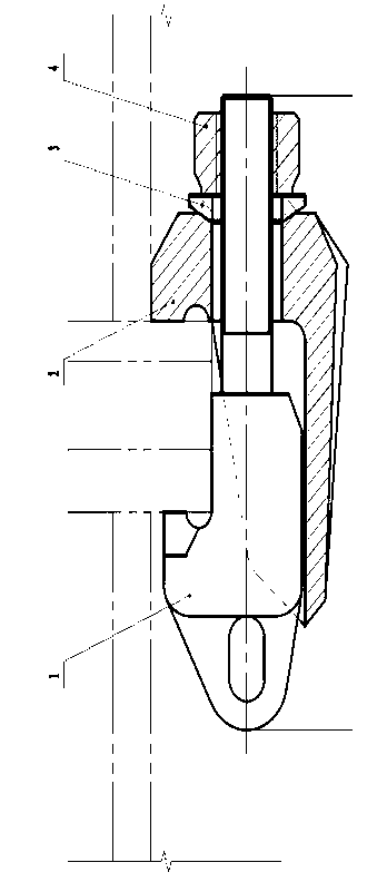
[0008] The specific embodiment of the present invention will be further described below in conjunction with accompanying drawing:

[0009] As shown in the accompanying drawings: a fixed clip device for a steelmaking vacuum tank, including a fixed clip 1, a movable ferrule 2, a spherical washer 3 and a high-strength nut 4, and the movable ferrule 2 is set on the fixed clip On the bolt 1, the movable ferrule 2 and the fixed ferrule 1 are locked by a high-strength nut 4, and a spherical washer 3 is arranged between the high-strength nut 4 and the movable ferrule 2, and the spherical washer 3 and the movable ferrule 2 adopt a spherical contact , the fixed clip 1 and the movable ferrule 2 are arranged with a plane jaw and an R surface.


PUM


Abstract

The invention discloses a fixing clamping bolt device for steelmaking vacuum groove. The device comprises a fixed clamping bolt, a movable cutting sleeve, a spherical washer and a high strength nut. The movable cutting sleeve is sleeved on the fixed clamping bolt; the movable cutting sleeve and the fixed clamping bolt are locked by the high strength nut; the spherical washer is arranged between the high strength nut and the movable cutting sleeve; and the spherical washer and the movable cutting sleeve are in spherical contact. The fixing clamping bolt device of the present invention does not oxidize or deform in high temperature, and is convenient for disassembly and replacement.

Description

technical field [0001] The invention relates to an RH vacuum tank system for steelmaking process equipment in the iron and steel industry, in particular to a fixing clamping device for a steelmaking vacuum tank. Background technique [0002] The original vacuum tank clamping device adopts conventional bolt connection and clamping, and the vacuum tank adopts conventional bolt connection clamping. The disadvantages are: 1. It is easy to deform, which cannot meet the sealing requirements and affects normal work; 2. Maintenance and disassembly are inconvenient, and maintenance is difficult. Contents of the invention [0003] The purpose of the present invention is to address the deficiencies of the prior art, to provide a fixed clamping device for the steelmaking vacuum tank, which ensures the sealing requirements of the vacuum tank, and solves the problem of easy corrosion and difficult disassembly when clamping with conventional bolts and replace. [0004] The technical sc...

Claims


Application Information

Patent Timeline
Patent Type & Authority Applications(China)
IPC IPC(8): C21C7/10
Inventor 何汝昌
Owner 江苏三嘉矿冶设备有限公司
Why Eureka
Try Eureka