Roller-type washing and drying machine

A washing-drying, drum-type technology, applied in washing devices, other washing machines, washing machines with containers, etc., can solve problems such as loud drainage noise, discomfort, and decreased drainage performance.

Active Publication Date: 2014-08-06
PANASONIC CORP
View PDF5 Cites 0 Cited by
  • Summary
  • Abstract
  • Description
  • Claims
  • Application Information

AI Technical Summary

Problems solved by technology

In this way, there is a problem that an uncomfortable loud discharge sound (residual water sound) is generated during dehydration due to turbulent flow, and the drainage performance is degraded.

Method used


Image

  • Roller-type washing and drying machine
  • Roller-type washing and drying machine
  • Roller-type washing and drying machine

Examples


Embodiment approach 1

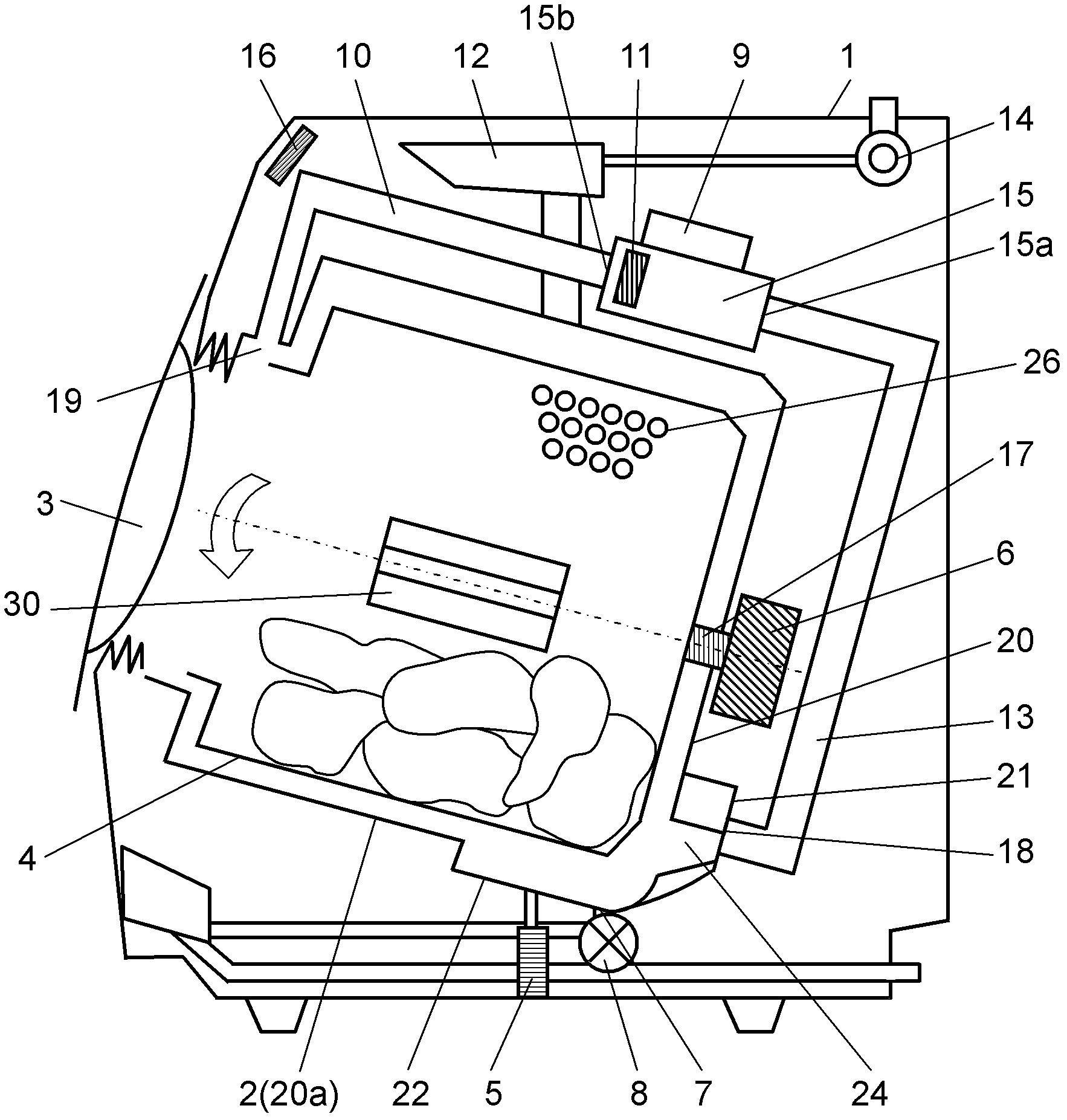
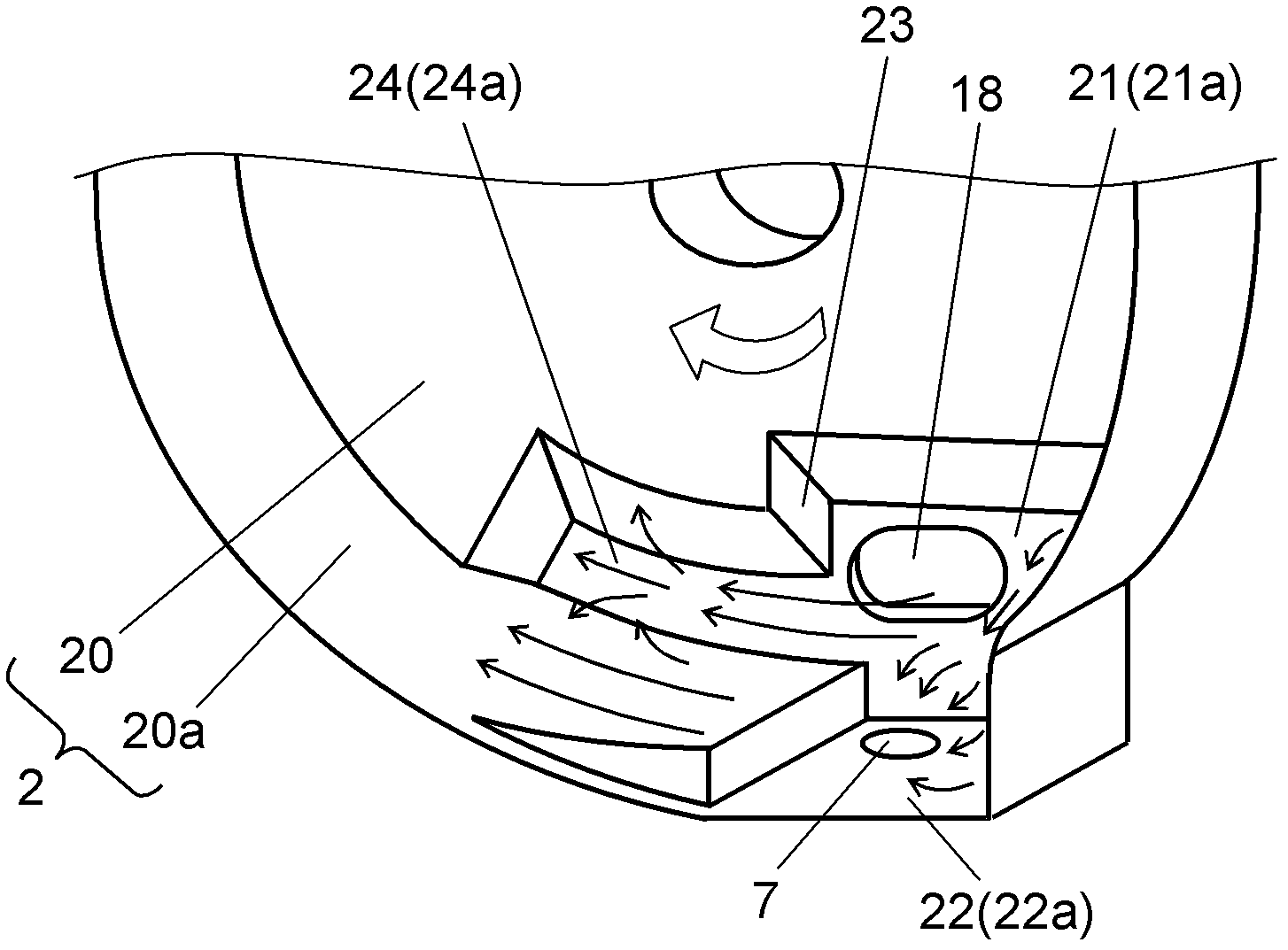
[0032] figure 1 It is a longitudinal sectional view of the drum type washing and drying machine in Embodiment 1 of this invention. figure 2 It is a partial detailed perspective view explaining the internal structure of the water tank of the drum type washing and drying machine in this embodiment.

[0033] Such as figure 1 As shown, the drum type washing and drying machine of this embodiment at least includes in the main body 1: a bottomed cylindrical water tank 2; a bottomed cylindrical rotating drum arranged in the water tank 2 in a freely rotatable manner. 4; and the cover 3 provided on a part of the main body 1 for taking and placing the laundry. A plurality of through-holes 26 are provided on the entire surface of the outer peripheral portion of the bottomed cylindrical rotating drum 4 , and are rotatably arranged in the water tank 2 . In addition, a plurality of protruding plates 30 are provided on the inner wall surface of the bottomed cylindrical rotating cylinder...

Embodiment approach 2

[0068] Below, use image 3 and Figure 4 , the drum-type washing and drying machine according to Embodiment 2 of the present invention will be described.

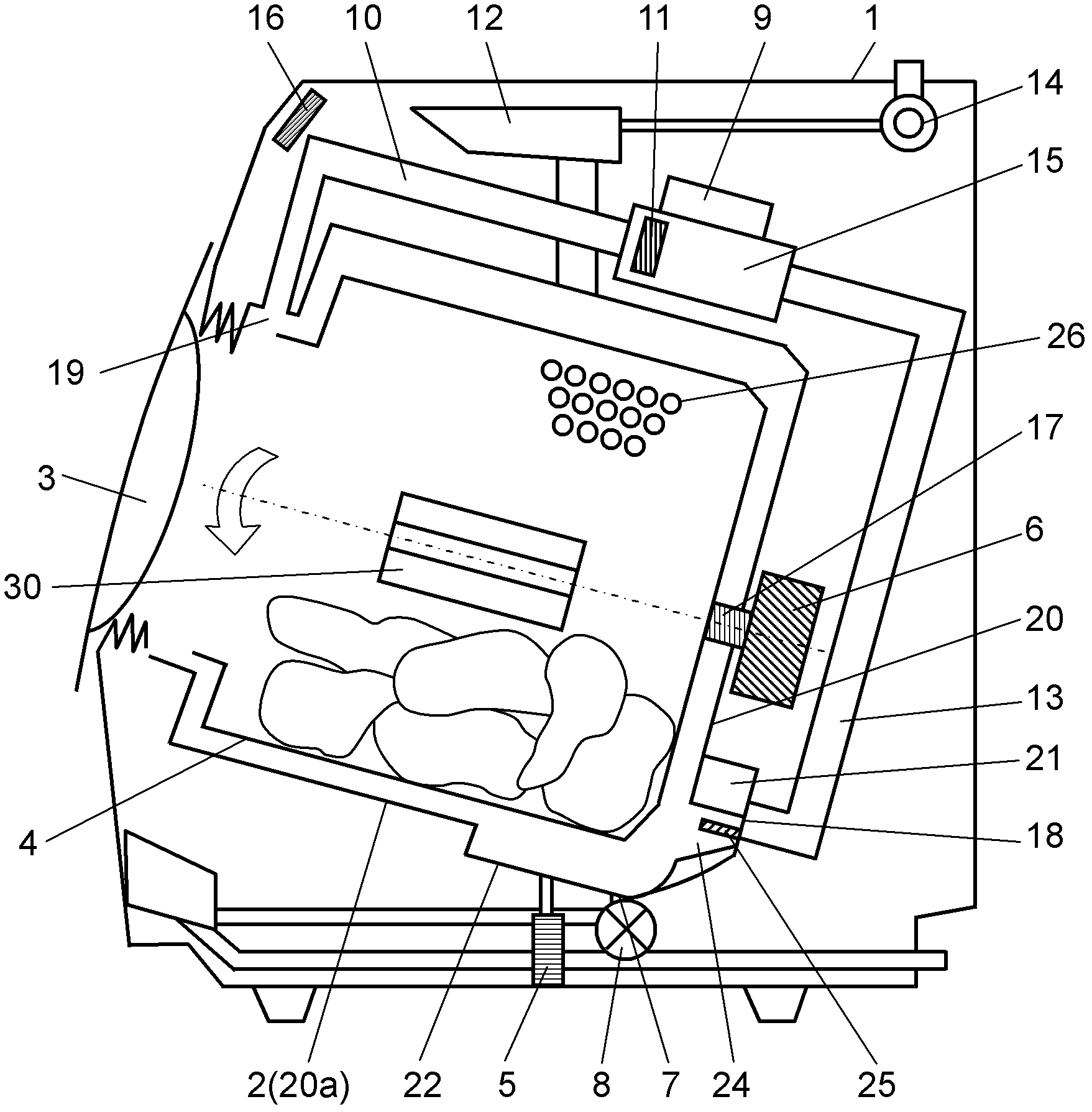
[0069] image 3 It is a longitudinal sectional view of the drum type washing and drying machine in Embodiment 2 of this invention. Figure 4 It is a partial detailed perspective view explaining the internal structure of the water tank of the drum type washing and drying machine in this embodiment.

[0070] Such as image 3 and Figure 4 As shown, the drum type washing and drying machine of the present embodiment is different from the first embodiment in that ribs are provided in the rotation direction along the water channel. The other configurations, functions, etc. are the same as those in Embodiment 1, and therefore description thereof will be omitted.

[0071] That is, if image 3 and Figure 4As shown, in the bottomed cylindrical water tank 2 , a part of the lower side of the substantially cylindrical side wall...


PUM


Abstract

The invention provides a roller-type washing and drying machine comprising a rotation barrel which has multiple through holes on surrounding walls, a water holding trough of the rotation barrel, an air supplying unit for supplying the air to the rotation barrel, a heating unti for heating the air, an air supplying path for guiding the heated air to the water holding trough, a heat exchange path for guiding the air to the air supplying unit and dehumidifying, and a control unit for controlling each process, wherein the water holding trough comprises a recess arranged on the back of the water holding trough, and a water path which extends along the rotating direction during the dehydration process and is connected with the recess; and as the turbulence is generated when the water in the crack between the undersurface of the rotation barrel and the back of the water holding trough runs into the fault wall of the recess of the water holding trough, the invention can prevent the situation during the dehydration process, thus significantly reducing the uncomfortable dewatering noise during the dehydration process and realizing stable performance for dewatering.

Description

technical field [0001] The present invention relates to a drum-type washing and drying machine which successively controls each process of cleaning, rinsing, dehydration, drying, etc. in a rotating drum with a rotating central axis in a substantially horizontal direction or an oblique direction. Background technique [0002] Existing this drum type washing and drying machine has the following uses Figure 5 and Image 6 The structure described. Figure 5 It is a longitudinal sectional view explaining the structure of the conventional drum type washing and drying machine. Image 6 It is a partially detailed perspective view illustrating the internal structure of a water tank (tub) of a conventional drum-type washing and drying machine. [0003] Such as Figure 5 As shown, the existing drum-type washing and drying machine at least includes in the main body 1: a bottomed cylindrical water tank 2 supported by a plurality of suspensions (Suspension, not shown in the figure) and ...

Claims


Application Information

Patent Timeline
Patent Type & Authority Patents(China)
IPC IPC(8): D06F25/00D06F37/20D06F37/06
Inventor 福田毅久保光市
Owner PANASONIC CORP
Why Eureka
Try Eureka