
Spiral pipe fixing component and sheathing method

A technology for spiral coils and fixing components, which is applied in the direction of pipes/pipe joints/fittings, pipe supports, mechanical equipment, etc., and can solve the problems of high precision parts manufacturing, insufficient strength of spiral coil fixing devices, and flow-induced vibration. , to achieve the effect of easy operation, ideal strength and precision, and simple implementation process

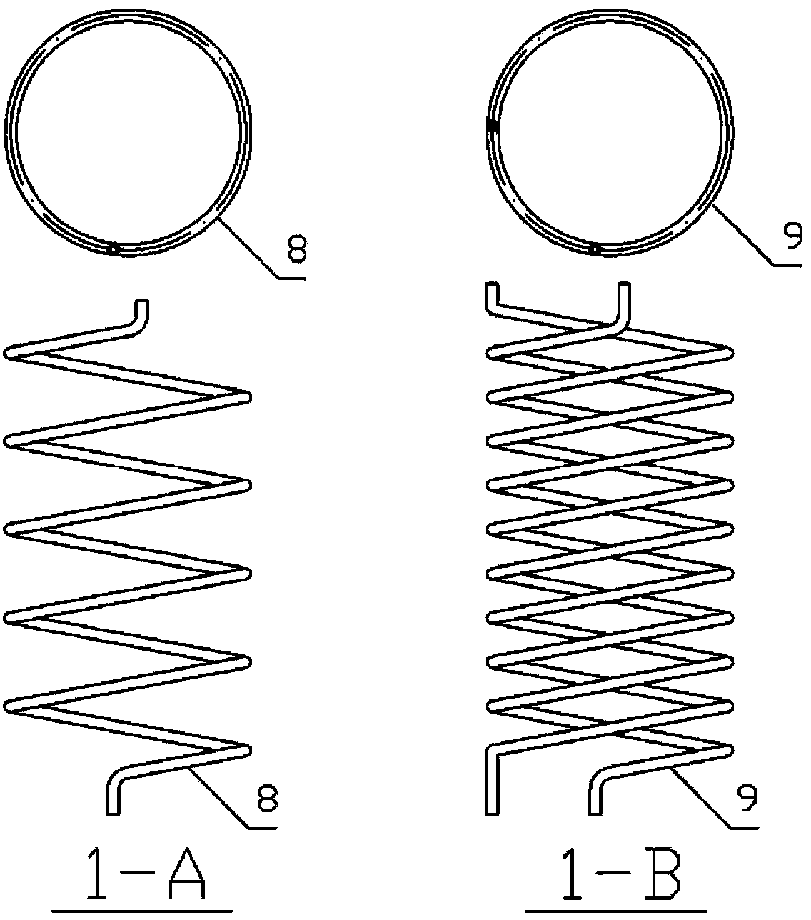
Active Publication Date: 2014-05-07
CHINERGY CO LTD
View PDF6 Cites 0 Cited by
  • Summary
  • Abstract
  • Description
  • Claims
  • Application Information

AI Technical Summary

Problems solved by technology

[0009] The purpose of the present invention is to solve the problems of insufficient strength of the existing spiral coil pipe fixing device, flow-induced vibration and excessive manufacturing precision requirements of parts and other problems.

Method used


Image

  • Spiral pipe fixing component and sheathing method
  • Spiral pipe fixing component and sheathing method
  • Spiral pipe fixing component and sheathing method

Examples


Embodiment 1

[0077] Solve the fixing problem of large-scale multi-layer multi-head spiral coil:

[0078] This embodiment needs to complete the package of a spiral coil heat exchanger, which is composed of 35 heat transfer tubes, the length of a single heat transfer tube is 60m, and the outer diameter and wall thickness are 19mm and 3mm respectively. The heat pipe material is P91. These heat transfer tubes are bent into spiral coils, adopting multi-layer spiral coil layout, divided into 5 layers, and the number of coil heads in each layer is 5, 6, 7, 8, 9 from the inside to the outside. The center diameter of each layer of coils is 350mm / 420mm / 490mm / 560mm / 630mm respectively, the gap between each layer of coils is 16mm, the gap between the upper and lower coils is 6m, and the coil height is about 6750mm; the total diameter It is 666mm. The Brinell hardness of the coil material P91 is 250HB; the material of the fixed component is Inconel800 (hardness below 140HB) or Inconel617 (hardness bel...

Embodiment 2

[0103] Solve the fixing problem of small and medium-sized single-layer double-ended spiral coils:

[0104] This embodiment needs to complete the set of a small spiral coil heat exchanger, the heat exchanger is composed of two heat transfer tubes, the length of a single heat transfer tube is 40m, the outer diameter and wall thickness are 22mm and 4mm respectively, The material of the heat transfer tube is SA213T23, and the hardness is about 190HB. The two heat transfer tubes of the heat exchanger adopt a single-layer double-headed spiral coil layout. The two heat transfer tubes spiral together. The outer diameter of the tube is 472mm, and the interval between the upper and lower adjacent coils is 8mm. The calculated value of the overall height of the coil is about 1700mm, and the outer diameter after putting on the outer sleeve is about 490mm.

[0105] The material selected for the fixing component in this embodiment is SA210 (hardness below 143HB), and the specific size and ...


PUM


Abstract

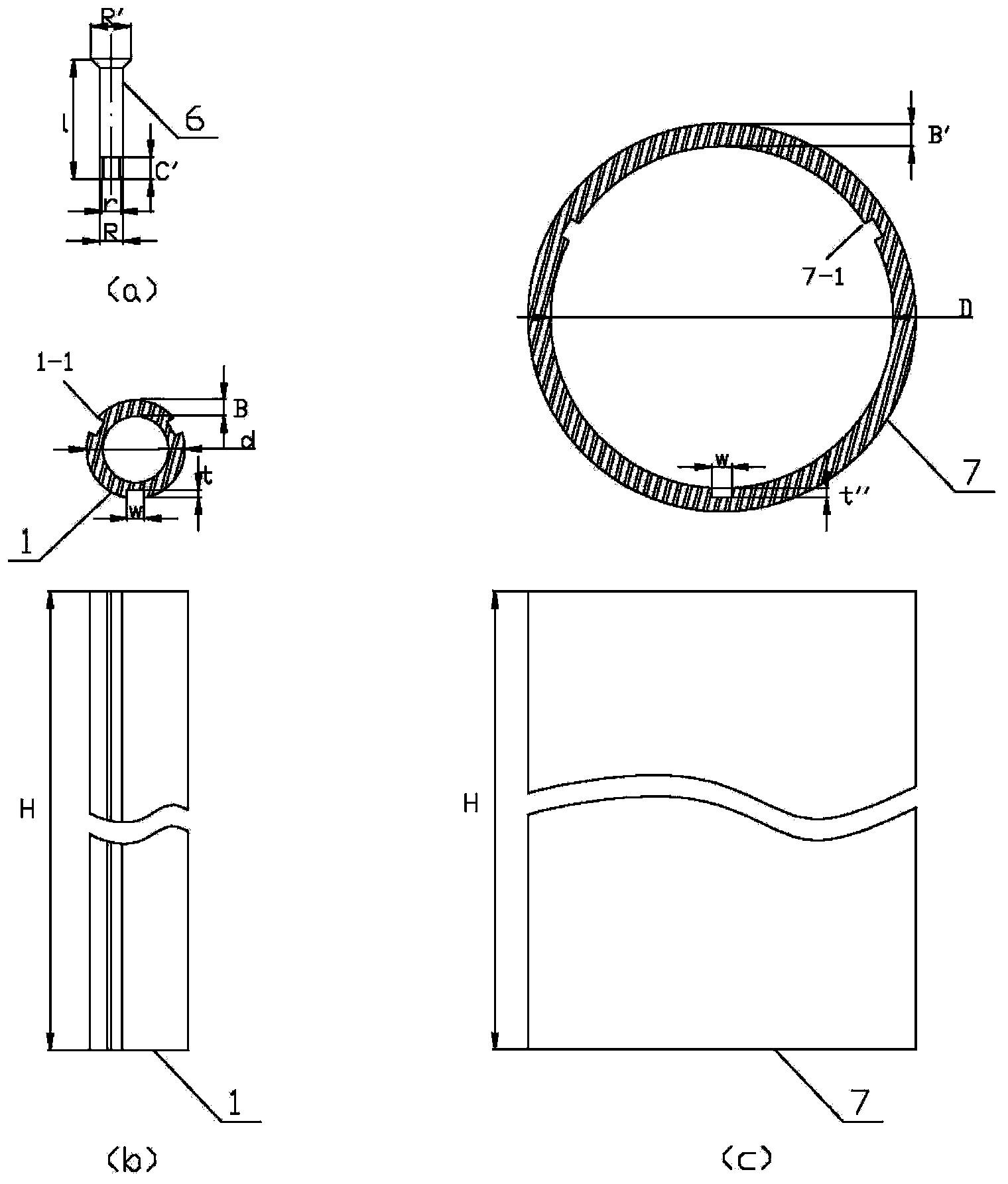
The invention relates to a spiral pipe fixing component and a sheathing method, belonging to the technical fields of sheathing and fixation of mechanical components. The fixing component mainly consists of an internal sleeve, an internal barrel bearing strip, a bearing strip, a fixing strip, fixing screws and an external sleeve. The sheathing method comprises following steps: embedding the internal barrel bearing strip into the recess of the internal sleeve; sheathing the first layer of spiral pipe on the outer side of the internal sleeve, placing the fixing strip on the outer side of the spiral pipe, pulling each of the fixing screws through each counter bore in the fixing strip, and screwing the fixing screws into screw holes in the internal sleeve bearing strip; adjusting concentricity; spot-welding the fixing screws and the fixing strip, and flatly polishing; clamping the bearing strip of the next layer of spiral pipe on the fixing strip in order that the fixing strip is embedded into the recess of the bearing strip; and completely sheathing all the layers. A process for manufacturing and assembling the component is simple; additionally, the sheathing method involves low requirement on the manufacturing precision of the component, and results in high stability and high strength to the fixed assembling of the spiral pipes; and therefore, the sheathing method is applicable for large-scale popularization and standardization.

Description

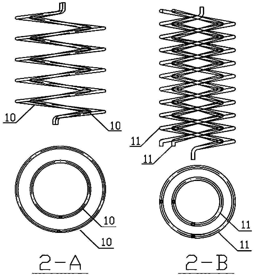
technical field [0001] The invention belongs to the technical field of fitting and fixing of mechanical parts, and relates to a method for fitting and fixing a spiral coil, especially for fitting and fixing a spiral coil with inner and outer multi-layer structures, which is applied to reactor steam generators, boilers, waste heat Large spiral coils for structures such as recovery units. Background technique [0002] Spiral coil is a common structure, which is widely used in pipeline transportation, chemical industry, electric power industry and other important industries, mainly for transporting fluid. At the same time, spiral coils are also a common design form of heat exchangers, so they are often used in equipment structures such as reactor evaporators, boilers, and waste heat recovery devices. [0003] Spiral coil, its shape features such as figure 1 , figure 2 As shown, for the sake of clarity, a group of spiral coils with the same coil diameter is defined as a laye...

Claims


Application Information

Patent Timeline
Patent Type & Authority Patents(China)
IPC IPC(8): F16L3/00
Inventor 孟东旺石琦汪垠邓志超白新文张素芬刘颖金东杰朱雨峰钟军李莹
Owner CHINERGY CO LTD
Learn More