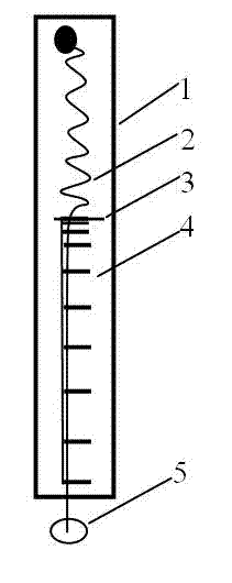
Simple spring balance teslameter
A spring scale, simple technology, applied to weighing equipment using elastically deformable parts, size/direction of magnetic field, measuring device, etc., can solve problems such as difficult movement, complex Tesla meter, easy to break, etc., and achieve low cost , The effect of measuring simple and fast, easy to move
Inactive Publication Date: 2012-10-17
SICHUAN UNIV
View PDF4 Cites 3 Cited by
- Summary
- Abstract
- Description
- Claims
- Application Information
AI Technical Summary
Problems solved by technology
[0002] The Tesla meter is more complex, bulky, and not easy to move
The probe is relatively delicate and easy to break
Method used
View moreImage
Smart ImageViewing Examples
Examples
Embodiment Construction
[0012] The stainless steel disc 5 touches the surface of the magnet, and the spring scale 1 is lifted upwards, the spring 2 is elongated, and the pointer 3 moves down. Note that the scale 4 pointed by the pointer immediately before the stainless steel disc 5 is pulled off is the maximum reading reached by the pointer.
Login to View More PUM
 Abstract
The invention discloses a simple spring balance teslameter, relates to the field of physical quantity measurement, and in particular to the rough estimation of a physical quantity. A teslameter is relatively complex and heavy and is not easy to move; and the probe is fine and easy to break. In order to rapidly and conveniently measure the approximate size of a magnetic field, a spring balance is adopted to measure the force of the magnetic field, and the magnitude of the magnetic field is judged according to the magnitude of the force. The technical scheme is that a stainless steel disc is arranged at the front end of the spring balance; the disc is contacted with the surface of a magnet; the spring balance is drawn till the stainless steel disc is disassociated from the surface of the magnet; the numerical value of the force at the moment of dissociation is recorded, i.e. the maximum value observed on the spring balance. The action force between the magnetic field and the stainless steel disc is F=B*B*S / (2u0), wherein B is the magnetic sensing strength; S is the contact area; u0 is the vacuum permeability; and F is the force. The simple spring balance teslameter has the beneficial effects of simple, rapid and convenient measurement, low cost and movement convenience.
Description
technical field [0001] The invention relates to the field of measurement of physical quantities, especially the rough estimation of physical quantities. Background technique [0002] Teslameters are more complicated, bulky, and not easy to move. Probes are delicate and easily broken. [0003] A spring balance can measure force with moderate accuracy. [0004] The magnetic field has a great relationship with the distance. The magnetic field is strong at a short distance and weak at a long distance. Therefore, in most cases, it is enough to only know the approximate size of the magnetic field. Contents of the invention [0005] In order to measure the approximate size of the magnetic field quickly and conveniently, the present invention uses a spring balance to measure the magnetic field force, and the size of the magnetic field is determined by the size of the force. [0006] The technical solution adopted by the present invention to realize the purpose of the invention ...
Claims
Login to View More Application Information
Patent Timeline
 Patent Type & Authority Applications(China)
IPC IPC(8): G01R33/02G01G3/00
Inventor 胡再国
Owner SICHUAN UNIV
Features
- R&D
- Intellectual Property
- Life Sciences
- Materials
- Tech Scout
- Unparalleled Data Quality
- Higher Quality Content
- 60% Fewer Hallucinations
Learn More Browse by: Latest US Patents, China's latest patents, Technical Efficacy Thesaurus, Application Domain, Technology Topic, Popular Technical Reports.
© 2025 PatSnap. All rights reserved.Legal|Privacy policy|Modern Slavery Act Transparency Statement|Sitemap|About US| Contact US: help@patsnap.com

