Eureka AIR delivers breakthrough ideas for toughest innovation challenges, trusted by R&D personnel around the world.

Lifting and descending device for electric energy meter checking device

A technology of lifting device and electric energy meter, which is applied in the direction of measuring device, measuring electric variables, instruments, etc., can solve the problems of inconvenient assembly and disassembly of meters, adjustment of photoelectric head, long distance of staff walking back and forth, and easy fatigue of staff, etc. Achieve the effect of small footprint, simple structure and compact device

Active Publication Date: 2012-10-17
南通海睿知新信息科技有限公司
View PDF9 Cites 6 Cited by
  • Summary
  • Abstract
  • Description
  • Claims
  • Application Information

AI Technical Summary

Problems solved by technology

[0002] The traditional lifting device used for electric energy meter verification device has at least two rows of meter positions on the upper and lower sides, and each row has at least two meter positions on the electric energy meter, so as to realize multi-meter position verification, because each The meter position is fixedly installed, and the distance between the upper and lower rows is relatively large. The upper row is too high and the lower row is too low. It is not convenient for the staff to assemble and disassemble the meter and adjust the photoelectric head. The site area is large, and the staff has a long distance to walk back and forth; on the other hand, due to the different heights of the staff who assemble and disassemble the meter, the appropriate height for the staff to mount the electric energy meter is different, and the working habits of different staff are different. The appropriate height of the meter is also different. Therefore, the staff of the traditional lifting device used for the calibration device of the electric energy meter are prone to fatigue. The electric energy meters in each row must be disassembled and calibrated at the same time, that is, when a certain row of electric energy meters is assembled and disassembled, the other row of electric energy meters cannot be calibrated, and the work efficiency is low. In order to improve the efficiency of electric energy meter inspection work and reduce the work Labor intensity of personnel, currently there are many kinds of automatic energy meter calibration devices or systems, but many kinds of fully automatic lifting device systems for energy meter calibration devices have a large station area and high cost, and can only calibrate electronic energy meters

Method used


Image

  • Lifting and descending device for electric energy meter checking device
  • Lifting and descending device for electric energy meter checking device
  • Lifting and descending device for electric energy meter checking device

Examples


Embodiment 1

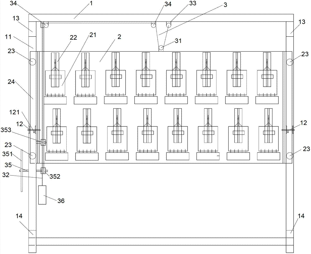
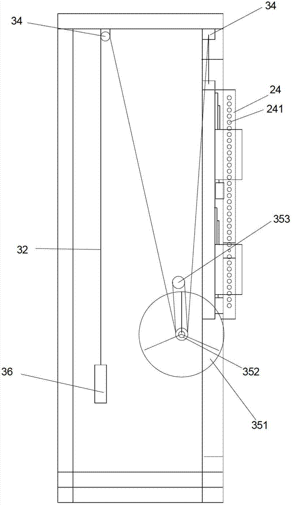
[0025] Such as figure 1 , figure 2 and Figure 5 Shown, a kind of lifting device that is used for electric energy meter detection device comprises fixed frame 1, is provided with movable plate 2 in fixed frame 1, and electric energy meter 21 is housed on movable plate 2, between fixed frame 1 and movable plate 2 There is a drive mechanism 3 for controlling the up and down movement of the movable plate 2. The drive mechanism 3 can control the movement of the movable plate 2 up and down on the fixed frame 1, so that the movable plate 2 stays at a suitable height, which is convenient for the staff to check the electric energy meter.

[0026] In the present invention, the driving mechanism 3 includes a movable pulley 31 arranged on the movable plate 2, a wire rope 32 passing through the movable pulley 31, a fixed ring 33 and a guide wheel 34 arranged on the fixed frame 1, and one end of the wire rope 32 is tied to the fixed On the ring 33, the other end passes through the movab...

Embodiment 2

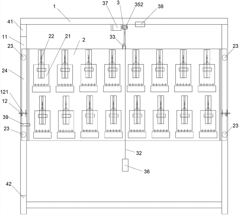
[0036] Such as image 3 , Figure 4 and Figure 5Shown, a kind of lifting device that is used for electric energy meter detection device comprises fixed frame 1, is provided with movable plate 2 in fixed frame 1, and electric energy meter 21 is housed on movable plate 2, between fixed frame 1 and movable plate 2 There is a drive mechanism 3 for controlling the up and down movement of the movable plate 2. The drive mechanism 3 can control the movement of the movable plate 2 up and down on the fixed frame 1, so that the movable plate 2 stays at a suitable height, which is convenient for the staff to check the electric energy meter.

[0037] In the present invention, the drive mechanism 3 includes a fixed ring 33 arranged above the frame of the movable plate 2, a self-locking reduction motor 37 arranged above the fixed frame 1, a pulling wheel 352 arranged at the shaft extension end of the self-locking reduction motor 37, One end is fixedly bolted to the steel wire rope 32 of t...


PUM


Abstract

The invention relates to a lifting and descending device for an electric energy meter checking device. The lifting and descending device is characterized by comprising a fixed frame (1), wherein a movable plate (2) is arranged in the fixed frame (1); electric energy meters (21) are arranged on the movable plate (2); and a driving mechanism (3) which controls the movable plate (2) to lift and descend vertically is arranged between the fixed frame (1) and the movable plate (2). When an operator needs to assemble or disassemble a certain row of electric energy meters, a hand wheel is rotated to drive a pull wheel to rotate, and a steel wire rope which is embedded in the pull wheel drives the movable plate to move vertically through friction, so the electric energy meters are moved to the most appropriate place by the operator, a positioning bolt is inserted into a positioning strip through hole and used for fixing the movable plate, and the operator can safely, conveniently and effortlessly assemble and disassemble the electric energy meters. The lifting and descending device for the electric energy meter checking device has the advantages that the electric energy meter checking device is in accordance with a man-machine engineering principle; the operator can conveniently and effortlessly assemble and disassemble the electric energy meters; and compared with a fully-automatic lifting and descending device, the lifting and descending device is high in working efficiency, simple in structure and low in cost.

Description

【Technical field】 [0001] The invention relates to a lifting device, in particular to a lifting device used for a verification device of an electric energy meter. 【Background technique】 [0002] The traditional lifting device used for electric energy meter verification device has at least two rows of meter positions on the upper and lower sides, and each row has at least two meter positions on the electric energy meter, so as to realize multi-meter position verification, because each The meter position is fixedly installed, and the distance between the upper and lower rows is relatively large. The upper row is too high and the lower row is too low. It is not convenient for the staff to assemble and disassemble the meter and adjust the photoelectric head. The site area is large, and the staff has a long distance to walk back and forth; on the other hand, due to the different heights of the staff who assemble and disassemble the meter, the appropriate height for the staff to mo...

Claims


Application Information

Patent Timeline
Patent Type & Authority Applications(China)
IPC IPC(8): G01R35/04
Inventor 陈劲游
Owner 南通海睿知新信息科技有限公司
Why Eureka
Eureka Blog
Learn More