Optical image lens assembly

An optical imaging and lens group technology, applied in optics, optical components, instruments, etc., can solve the problems of large power consumption, limited focal depth, and long overall optical length of the overall lens module, and achieve good control and low driving power. Effect

Active Publication Date: 2012-10-17
LARGAN PRECISION
View PDF7 Cites 4 Cited by
  • Summary
  • Abstract
  • Description
  • Claims
  • Application Information

AI Technical Summary

Problems solved by technology

However, this lens group has a limited depth of focus for focusing at very close range, so its image quality has the disadvantage of peripheral image blur
As disclosed in U.S. Patent No. 7,777,972, this invention is an imaging lens group with a two-group lens structure, but its second lens group is only equipped with three lenses, so the ability to correct aberrations or chromatic aberrations is still insufficient
In addition, for a photographic lens with a focus adjustment function, the focus adjustment method is to use a drive motor to change the relative distance between the overall photographic lens and the image sensor. Since the entire photographic lens must be driven, the power consumption is relatively large, and the overall The overall optical length of the lens module is also longer

Method used


Image

  • Optical image lens assembly
  • Optical image lens assembly
  • Optical image lens assembly

Examples


no. 1 example

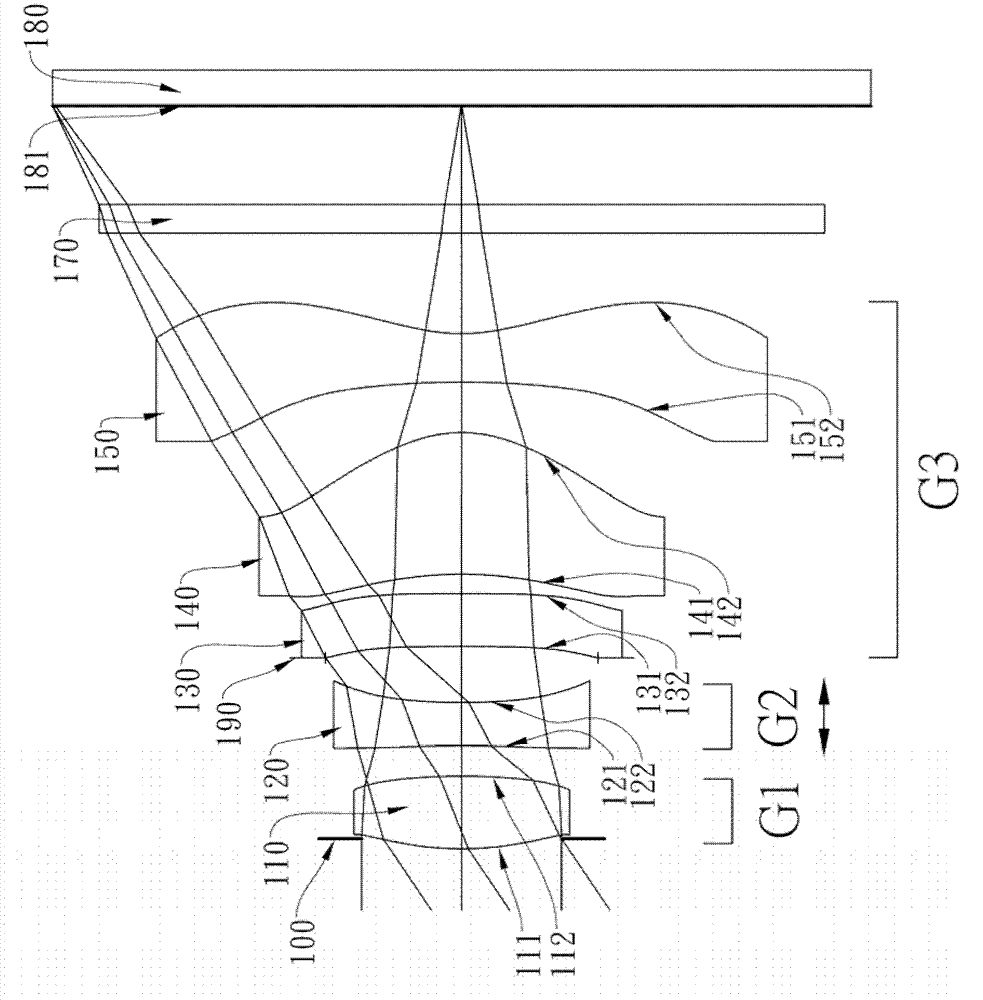
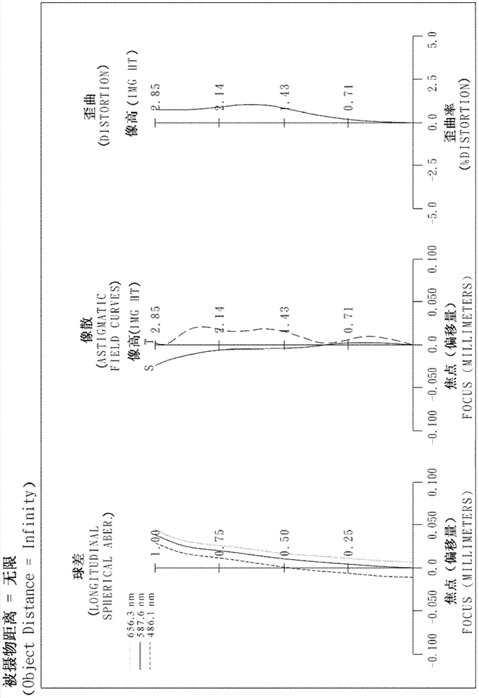
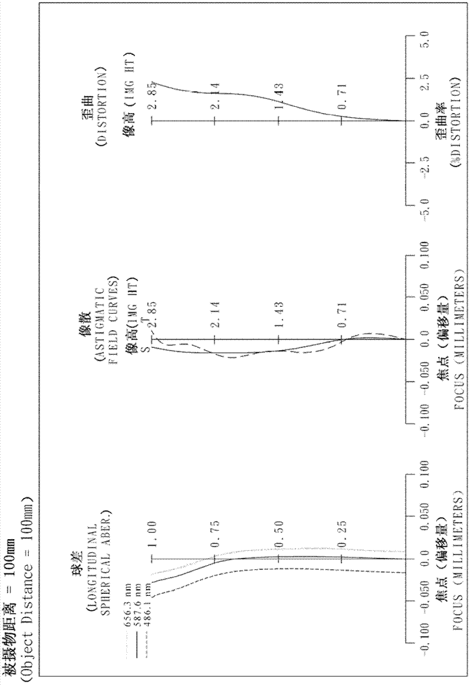
[0106] Please refer to the first embodiment of the present invention Figure 1A , for the aberration curve of the first embodiment, please refer to Figure 1B (subject distance is infinite) and Figure 1C (The subject distance is 100mm). The optical imaging lens group of the first embodiment is mainly composed of five lenses, which include in sequence from the object side to the image side:

[0107] A first lens group G1, which includes a first lens 110 with positive refractive power, its object side 111 is a convex surface and its image side 112 is a convex surface, and its material is plastic. The object side 111 and image side of the first lens 110 112 are all aspheric;

[0108] A second lens group G2, which includes a second lens 120 with negative refractive power, its object side 121 is concave and its image side 122 is concave, and its material is plastic. The object side 121 and image side of the second lens 120 122 are all aspheric; and

[0109] A third mirror grou...

no. 2 example

[0143] Please refer to the second embodiment of the present invention Figure 2A , for the aberration curve of the second embodiment, please refer to Figure 2B (subject distance is infinite) and Figure 2C (The subject distance is 100mm). The optical imaging lens group of the second embodiment is mainly composed of five lenses, which sequentially include from the object side to the image side:

[0144] A first lens group G1, which includes a first lens 210 with positive refractive power, its object side 211 is a convex surface and its image side 212 is a convex surface, and its material is plastic. The object side 211 and image side of the first lens 210 212 are all aspheric;

[0145] A second lens group G2, which includes a second lens 220 with negative refractive power, the object side 221 is convex and the image side 222 is concave, and its material is plastic. The object side 221 and the image side of the second lens 220 222 are both aspherical; and

[0146] A third ...

no. 3 example

[0160] Please refer to the third embodiment of the present invention Figure 3A , for the aberration curve of the third embodiment, please refer to Figure 3B (subject distance is infinite) and Figure 3C (The subject distance is 100mm). The optical imaging lens group of the third embodiment is mainly composed of five lenses, which sequentially include from the object side to the image side:

[0161] A first lens group G1, which includes a first lens 310 with positive refractive power, the object side 311 and the image side 312 are convex, and its material is plastic. The object side 311 and the image side of the first lens 310 312 are all aspherical;

[0162] A second lens group G2, which includes a second lens 320 with negative refractive power, its object side 321 is concave and its image side 322 is concave, and its material is plastic. The object side 321 and image side of the second lens 320 322 are both aspherical; and

[0163] A third mirror group G3, including in...


PUM


Abstract

This invention provides an optical image lens assembly in order from an object side to an image side comprising: a first lens group that has a first lens element with positive refractive power; a second lens group that has a second lens element with negative refractive power; and a third lens group that has at least three lens elements with refractive power; wherein a lens element in the third lens group closest to an image plane has negative refractive power and a concave image-side surface; wherein while a distance between an imaged object and the optical image lens assembly changes from far to near, focusing is performed by moving the second lens group along the optical axis toward the image plane. By such arrangement and focusing adjustment method, good image quality is achieved and less power is consumed.

Description

technical field [0001] The invention relates to an optical image lens group; in particular, it relates to a miniaturized optical image lens group applied to electronic products. Background technique [0002] The photosensitive element of a general photographic lens is nothing more than a photosensitive coupled device (Charge Coupled Device, CCD) or a complementary metal-oxide semiconductor (Complementary Metal-Oxide Semiconductor, CMOS). In recent years, with the rise of mobile phone cameras, the demand for miniaturized photography lenses has been increasing. At the same time, due to the advancement of semiconductor process technology, the pixel area of ​​the photosensitive element has been reduced, leading the miniaturization of photographic lenses to gradually develop into the field of high pixel. [0003] Traditional miniaturized photographic lenses mounted on mobile phone cameras usually have a fixed focus, that is, fixed-focus lenses. Therefore, at a specific object d...

Claims


Application Information

Patent Timeline
Patent Type & Authority Applications(China)
IPC IPC(8): G02B13/18G02B13/00G02B13/22
CPCG02B13/0045
Inventor 黄歆璇
Owner LARGAN PRECISION
Why Eureka
Try Eureka