
Method for automatically starting central processing unit (CPU) system by utilizing double flashes

An automatic and code-starting technology, applied in the direction of program loading/starting, generation of response errors, error detection of redundant data in operation, etc., can solve problems such as boot failure, system startup failure, startup failure, etc., to achieve reliable High performance, simple operation and strong controllability

Inactive Publication Date: 2012-10-17
INFORMATION & COMMNUNICATION BRANCH STATE GRID JIANGXI ELECTRIC POWER CO
View PDF5 Cites 17 Cited by
  • Summary
  • Abstract
  • Description
  • Claims
  • Application Information

AI Technical Summary

Problems solved by technology

This method of starting the CPU with a single FLASH is to burn the boot program bootrom into the FLASH during factory production, and then the bootrom will guide the application to start. Online upgrade of the bootrom and application programs will cause the system to fail due to the following reasons, and the problem must be solved by returning to the factory and re-burning: 1. When upgrading the bootrom, when the power is suddenly cut off or the upgrade fails for other reasons, the Boot program error; 2. The problem of the FLASH chip itself, after a certain number of reads and writes, some areas of the FLASH have errors, causing boot failure; upgrading the wrong bootrom program to the FLASH, resulting in startup failure
Once the bootrom fails to start, it will cause major failures to project implementation because the site cannot be rolled back or restored

Method used


Image

  • Method for automatically starting central processing unit (CPU) system by utilizing double flashes
  • Method for automatically starting central processing unit (CPU) system by utilizing double flashes
  • Method for automatically starting central processing unit (CPU) system by utilizing double flashes

Examples


Embodiment Construction

[0013] The present invention will be further described in detail below in conjunction with the accompanying drawings and specific examples.

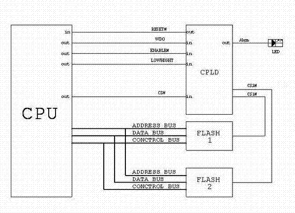
[0014] A method for automatically starting a CPU system with dual FLASH. Before leaving the factory, the two FLASHs are programmed with a startup program bootrom and a complete application program of the entire system.

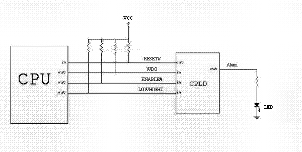
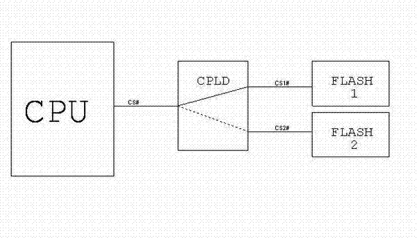
[0015] Such as figure 2 Shown, the control handshake schematic diagram between CPU and CPLD that the present invention adopts, RESET# among the figure resets the reset signal of whole CPU system for CPLD; A pulse wave with a period of 1S. ENABLE# is for authorized users who need to upgrade FLASH and control the CPU by command to pull down the signal to enable the upgrade function, and then CPLD determines to switch the CPU chip selection CS# to CS1# or CS2# by reading the LOW / HIGHT signal; image 3 shown in image 3 The middle CPLD is equivalent to a toggle switch. If the CPU sets LOW / HIGHT to high level (default), t...


PUM


Abstract

The invention relates to a method for automatically starting a central processing unit (CPU) system by utilizing double flashes. Two flashes are adopted to start the CPU, when a main flash fails to start the CPU, a complex program logic device (CPLD) selects a reserved flash and outputs a reset signal to the CPU so as to enable the CPU to be started from the reserved flash. The flash is required to upgrade after the CPU is started, the CPU sets that only an authorized user can start the CPULD to upgrade the reading and writing of the main and the reserved flashes, and thus the error operation of the user can be avoided, and the product reliability can be greatly improved. Due to the adoption of the method, under the situation that one flash cannot be started, the reserved flash can be automatically switched to guide the normal starting of the CPU, the normal starting of the CPU can be automatically and intelligently completed without adding the manual switching way such as a shifting code switch or a button, the main and the reserved flashes are automatically and intelligent switched, simplicity in operation is realized, the controllability is strong, and the reliability is high.

Description

technical field [0001] The invention relates to an embedded CPU system domain, in particular to a method for realizing automatic double FLASH startup of a CPU system. Background technique [0002] The general practice in today's embedded system applications is to use a single FLASH boot to guide the CPU to load the bootrom and application program version, and this method is widely used in the embedded platform of communication equipment. This method of starting the CPU with a single FLASH is to burn the boot program bootrom into the FLASH during factory production, and then the bootrom will guide the application to start. Online upgrade of the bootrom and application programs will cause the system to fail due to the following reasons, and the problem must be solved by returning to the factory and re-burning: 1. When upgrading the bootrom, when the power is suddenly cut off or the upgrade fails for other reasons, the Boot program error; 2. The problem of the FLASH chip itsel...

Claims


Application Information

Patent Timeline
Patent Type & Authority Applications(China)
IPC IPC(8): G06F9/445G06F11/14
Inventor 李健
Owner INFORMATION & COMMNUNICATION BRANCH STATE GRID JIANGXI ELECTRIC POWER CO
Learn More