Lead storage battery

A lead-acid battery and single-battery technology, applied in lead-acid battery, lead-acid battery construction, battery and other directions, can solve the problems of deep discharge depth, capacity reduction, battery scrapping, etc. Effects of stress corrosion

Active Publication Date: 2014-03-05
松下蓄电池(沈阳)有限公司 +1
View PDF9 Cites 1 Cited by
  • Summary
  • Abstract
  • Description
  • Claims
  • Application Information

AI Technical Summary

Problems solved by technology

The technical problem to be solved is: during the use of the lead-acid battery, the stretching of the positive plate is prone to occur, and the stretching cannot be fully absorbed by the saddle, and the bending of the above-mentioned positive plate will cause it to disjoint with the adjacent negative electrode. A short circuit occurs between the plates, resulting in reduced capacity and battery failure
Since the electric vehicle cannot charge the battery while driving, the longer the driving distance, the deeper the discharge depth, and it is necessary to frequently brake and start with a large current when facing traffic lights during driving, even when the battery is low. It is still necessary to start with a large current, which is most likely to cause over-discharge

Method used


Image

  • Lead storage battery
  • Lead storage battery
  • Lead storage battery

Examples


Embodiment approach 1

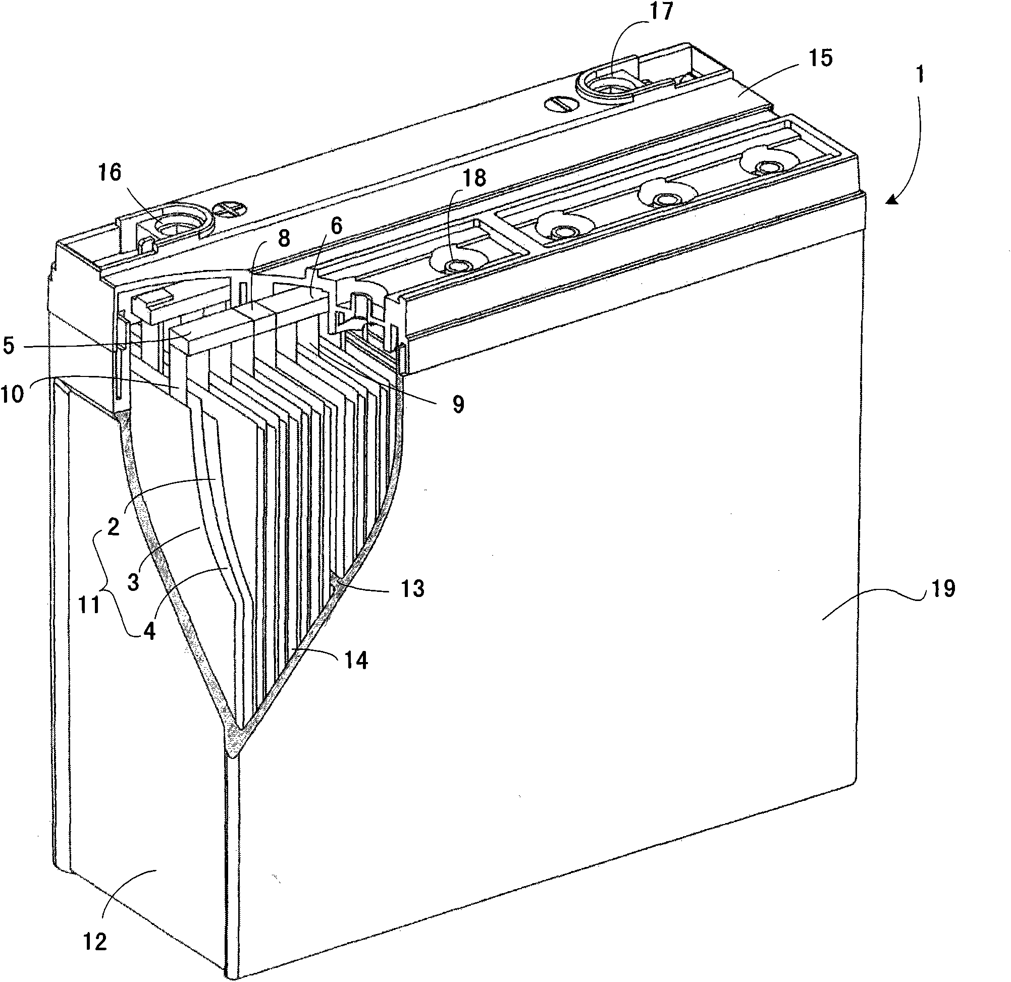
[0081] The lead storage battery 1 of Embodiment 1 has a plurality of unit cells 12, and each unit cell 12 has a pole plate group 11, an electrolyte solution (not shown) and a unit cell chamber 14, and the above-mentioned pole plate group 11 is immersed in The state of the electrolyte solution is accommodated in the above-mentioned single cell chamber 14, and the above-mentioned plate group 11 is formed by alternately arranging a plurality of positive plates 2 and a plurality of negative plates 3 with separators 4 interposed therebetween. A positive electrode current collector and a positive electrode active material layer held by the positive electrode current collector, each negative plate includes a negative electrode current collector with tabs and a negative electrode active material layer held by the above negative electrode current collector, characterized in that, The positive bus bar of the positive plate and the negative bus bar of the negative plate of each single bat...

Embodiment approach 2

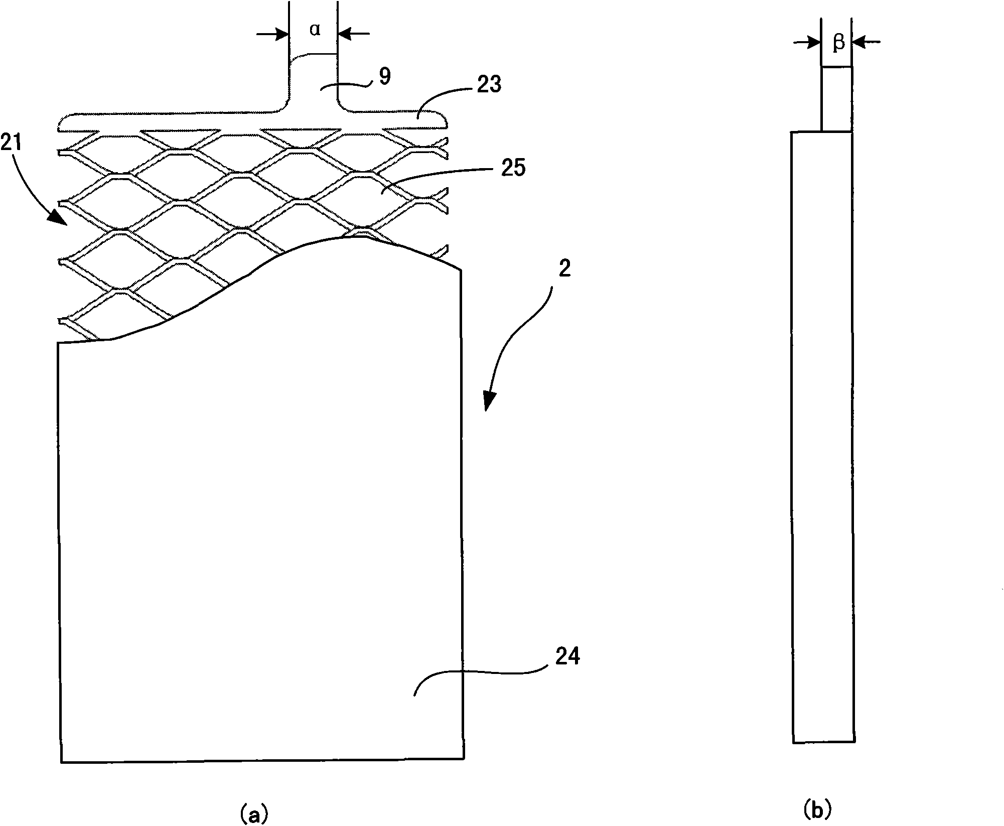
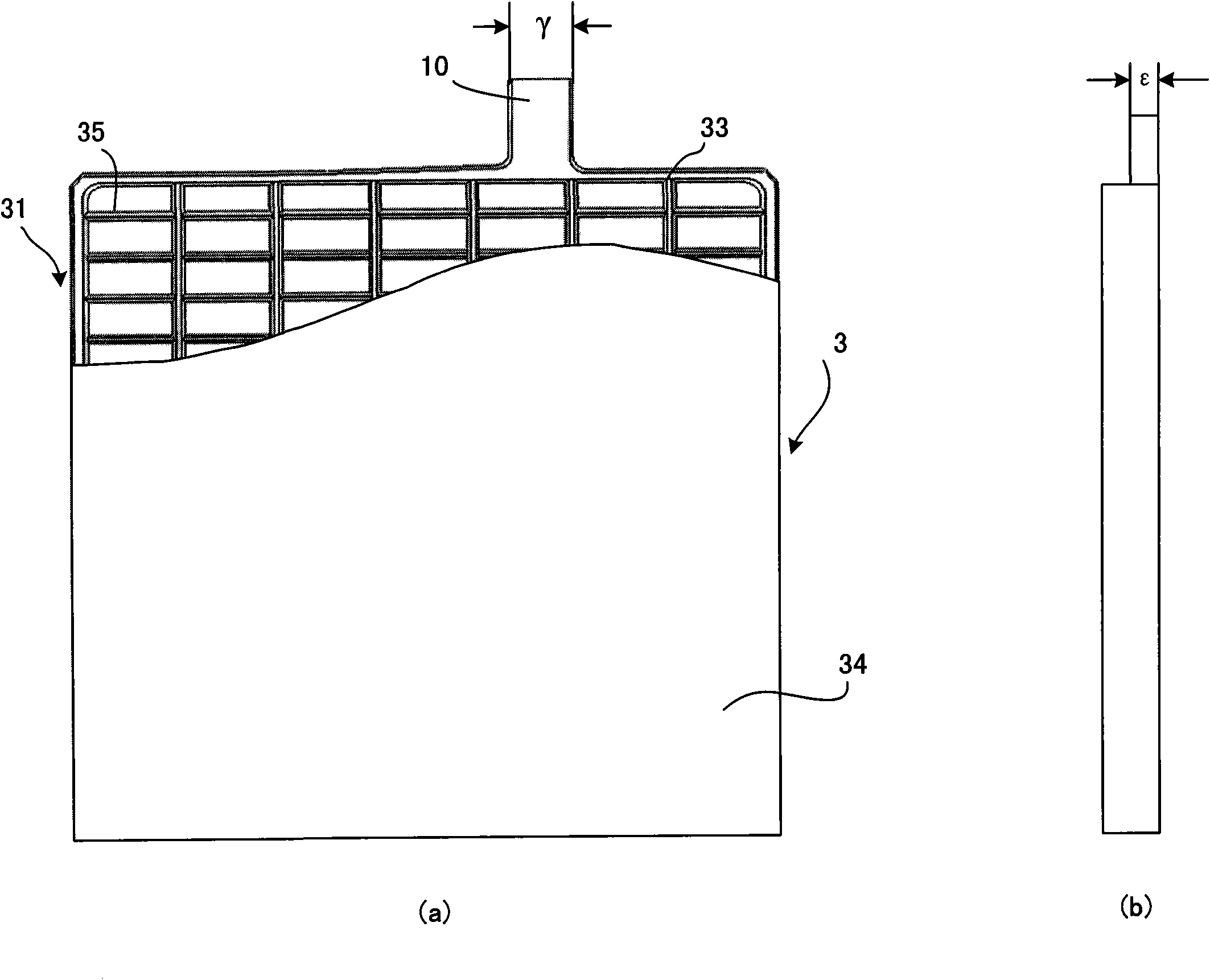
[0084] The lead storage battery 1 of Embodiment 2 is based on the lead storage battery 1 of Embodiment 1, further setting the thickness of the tabs of each of the above-mentioned positive plates to be smaller than the thickness of the tabs of the above-mentioned negative plates, or the thickness of the above-mentioned multiple positive plates. The total thickness of the tabs is less than the total thickness of the tabs of the above-mentioned multiple negative plates, wherein the thickness of the tabs of each of the above-mentioned positive plates is 1.0-2.0 mm, preferably 1.2-1.8 mm; the tab of each of the above-mentioned negative plates The thickness is 1.2-2.5 mm, preferably 1.3-2.0 mm.

[0085] According to the final technical effect to be achieved, other constituent elements can be appropriately selected from the foregoing detailed description.

Embodiment approach 3

[0087] The lead storage battery 1 of Embodiment 3 is based on the lead storage battery 1 of Embodiment 1, and further assumes that the above-mentioned positive electrode current collector is an expanded mesh grid made by a reciprocating cutting method, so that the tortuosity T of the grid is / W is in the range of 1.60 to 1.80, and the negative electrode current collector is a grid made by casting. Moreover, it is preferable to set the ratio P / T which shows the paste overfill rate on the said expanded-grid to the range of 1.14-1.30.

[0088] According to the final technical effect to be achieved, other constituent elements can be appropriately selected from the foregoing detailed description.


PUM

PropertyMeasurementUnit
widthaaaaaaaaaa
widthaaaaaaaaaa
thicknessaaaaaaaaaa

Abstract

An objective of the present invention is to provide a lead-acid storage battery with which it is possible to carry out a high rate discharge and which has a long life even in a shallow state of charge (SOC). The present invention is a lead-acid storage battery (1) comprising a plurality of unit cells (12). The unit cell (12) further comprises: an electrode plate group (11) wherein a plurality of positive electrode plates (2) and a plurality of negative electrode plates (3) are alternately arrayed with separators (4) interposed therebetween; and a unit cell substance (14) which houses the electrode plate group (11) together with an electrolyte. In the unit cell (12), the plurality of positive electrode plates (2) is connected in parallel with a positive electrode bus bar (6) which is connected to tab parts (9). The plurality of negative electrode plates (3) is connected in parallel with a negative electrode bus bar (5) which is connected to tab parts (10). A ratio (K / L) of a tab part cross-section area (K) of the positive electrode plate (2) to a tab part cross-section area (L) of the negative electrode plate (3) is 0.6 = K / L < 1.0. In adjacent unit cells (12), the positive electrode bus bar (6) of one unit cell (12) and the negative electrode bus bar (5) of another unit cell are directly connected.

Description

technical field [0001] The invention relates to a lead storage battery. More specifically, the present invention relates to lead storage batteries for mains power applications. Background technique [0002] In addition to being used as a power source for starting vehicles and as a backup power source, lead-acid batteries are also widely used as main power sources, that is, as power sources for independent charging and discharging equipment such as electric vehicles, electric bicycles, electric motorcycles, electric scooters, small Power sources for electric mopeds, golf carts, etc., batteries for solar energy, etc. In these applications, the working characteristics of lead-acid batteries are: large current when starting, small discharge current when driving, and long discharge time. At the same time, it is also required to reduce the maintenance of lead-acid batteries, especially to have a longer service life. In terms of battery life extension, the usual practice is to i...

Claims


Application Information

Patent Timeline
Patent Type & Authority Patents(China)
IPC IPC(8): H01M2/28H01M4/73H01M50/541H01M50/51H01M50/516H01M50/529
CPCH01M2220/20H01M2010/4292Y02E60/126H01M2/206H01M4/70Y02T10/7016H01M2/28H01M10/12H01M2/266Y02E60/10H01M50/541Y02P70/50H01M50/51H01M50/516
Inventor 王世龙迟峥白松涛安藤和成佐佐木健浩室地省三
Owner 松下蓄电池(沈阳)有限公司
Why Eureka
Try Eureka