Driving power supply control circuit

A control circuit and drive power technology, applied in the field of LED lighting, can solve problems such as inability to make inventory, incompatibility, and cost a lot of money, so as to reduce manpower and material costs, ensure supply quality, and improve production efficiency.

Inactive Publication Date: 2012-10-17
SHANXI ZHAOXIN ELECTRIC POWER EQUIP
View PDF4 Cites 20 Cited by
  • Summary
  • Abstract
  • Description
  • Claims
  • Application Information

AI Technical Summary

Problems solved by technology

[0002] Nowadays, there are many types of serial and parallel LED optical group modules, and there are also quite a lot of current and voltage requirements for the driving power supply. This puts a lot of pressure on the design, production and supply of materials for professional manufacturers of driving power supplies.
Often professional LED lighting manufacturers require short, smooth and fast delivery of the driving power supply. Since the LED loads of various LED lighting manufacturers are connected in series and parallel in various ways, the voltage and current of the driving power supply also change with the change of the LED module. There is a relative process from design to production of driving power (reliability verification is required), so professional driver manufacturers cann

Method used


Image

  • Driving power supply control circuit
  • Driving power supply control circuit
  • Driving power supply control circuit

Examples


Example Embodiment

[0024] The technical solutions in the embodiments of the present invention will be clearly and completely described below in conjunction with the accompanying drawings in the embodiments of the present invention. Obviously, the described embodiments are only a part of the embodiments of the present invention, rather than all the embodiments. Based on the embodiments of the present invention, all other embodiments obtained by those of ordinary skill in the art without creative work shall fall within the protection scope of the present invention.

[0025] In addition, in order to better illustrate the present invention, numerous specific details are given in the following specific embodiments. Those skilled in the art should understand that the present invention can also be implemented without these specific details. In some other embodiments, well-known methods, means, components, and circuits are not described in detail in order to highlight the gist of the present invention.
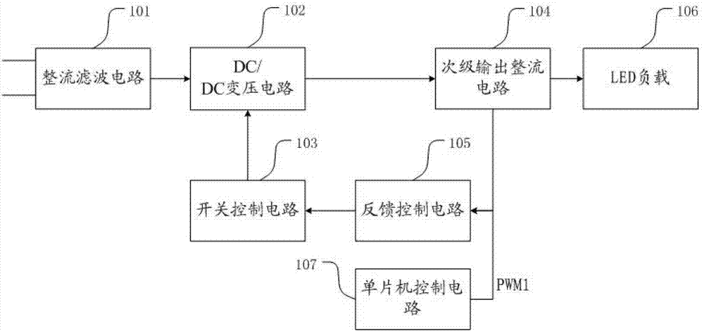
[0...


PUM


Abstract

The invention discloses a driving power supply control circuit. The driving power supply control circuit comprises a rectifier filter circuit, a DC/DC (Direct Current to Direct Current) transformation circuit, a switching control circuit, a feedback control circuit and a secondary output rectifier circuit. The feedback control circuit is connected between the secondary output rectifier circuit and the switching control circuit; the voltage sampling end of the feedback control circuit is connected with a singlechip control circuit; the singlechip control circuit is used for generating a control signal PWM1 to control a feedback voltage output of the feedback control circuit; and the singlechip control circuit can also be used for generating a load current control signal PWM2 for a load current control circuit to regulate the average of an output current cycle. According to the driving power supply control circuit provided by the invention, the mass production of a manufacturer can be ensured, the matching can be implemented only by carrying out program updating on a singlechip chip for different LED (Light-Emitting Diode) loads, the manpower and material cost is reduced, the production efficiency is improved and the supply quality is also ensured.

Description

technical field [0001] The invention relates to the technical field of LED lighting, in particular to a driving power supply control circuit capable of controlling LED loads. Background technique [0002] Nowadays, there are many kinds of series and parallel LED optical group modules, and there are quite a lot of current and voltage requirements for the driving power supply. This puts a lot of pressure on the design, production and material supply of professional manufacturers of driving power supplies. Often professional LED lighting manufacturers require short, smooth and fast delivery of the driving power supply. Since the LED loads of various LED lighting manufacturers are connected in series and parallel in various ways, the voltage and current of the driving power supply also change with the change of the LED module. There is a relative process from design to production of driving power (reliability verification is required), so professional driver manufacturers cannot...

Claims


Application Information

Patent Timeline
IPC IPC(8): H05B37/02
Inventor 涂道平
Owner SHANXI ZHAOXIN ELECTRIC POWER EQUIP
Why Eureka
Try Eureka