Electric servo device and brake device employing same

A booster device, electric technology, applied in the direction of braking transmission device, using electric device, using electromagnetic means, etc., can solve the problem of loss of load and other problems, achieve the effect of reducing the installation space, reducing the number of parts, and simple structure

Inactive Publication Date: 2012-10-17
BOSCH CORP
View PDF7 Cites 4 Cited by
  • Summary
  • Abstract
  • Description
  • Claims
  • Application Information

AI Technical Summary

Problems solved by technology

Also, even if the brake hydraulic pressure is generated, the brake cylinder is not activated immediately, i.e. there is a loss load in the brake system

Method used


Image

  • Electric servo device and brake device employing same
  • Electric servo device and brake device employing same
  • Electric servo device and brake device employing same

Examples


Embodiment Construction

[0025] Hereinafter, modes for implementing the present invention will be described using the drawings.

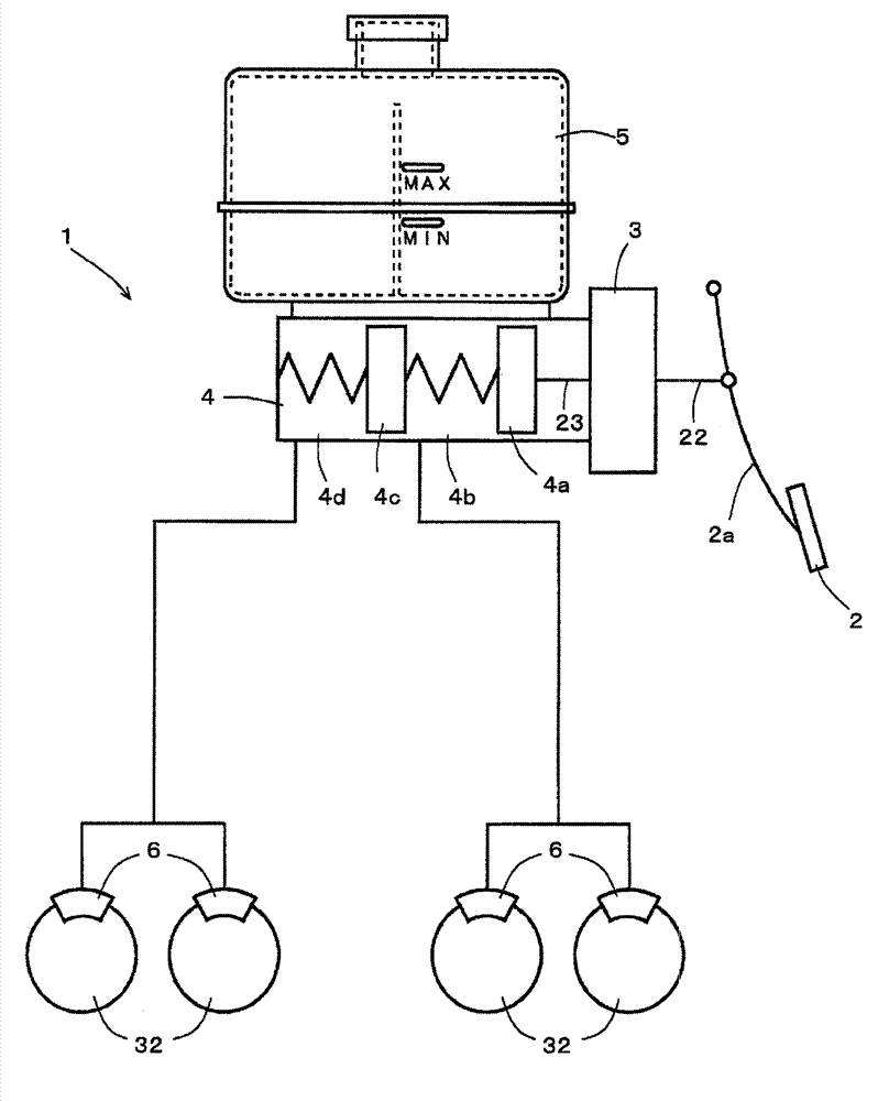
[0026] figure 1 It is a figure which schematically shows the braking device which has an example of embodiment of the electric booster of this invention.

[0027] Such as figure 1 As shown, the brake device 1 of this example is basically the same as a conventionally known general two-system brake device. That is, the brake device 1 includes a brake pedal 2 , an electric booster 3 , a tandem master cylinder 4 , a storage tank 5 , and a brake cylinder 6 .

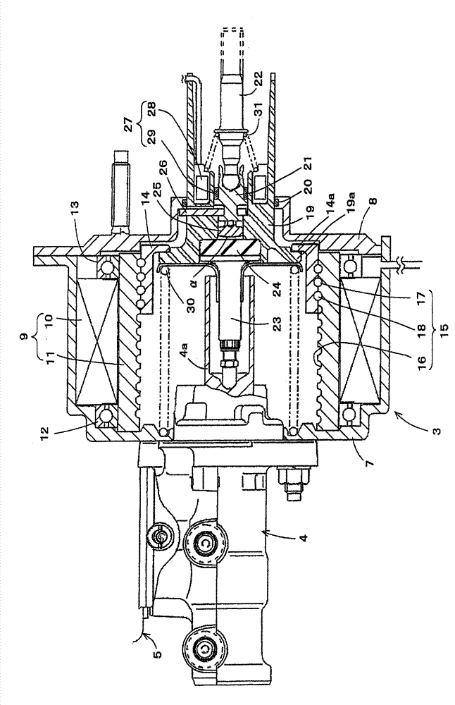
[0028] Such as figure 2 As shown, the electric booster 3 of this example has a front case 7 and a rear case 8 connected to each other. An electric motor 9 is arranged inside the front case 7 . The electric motor 9 has a stator 10 and a rotor 11, wherein the stator 10 is an annular magnetic force generating part composed of a coil fixedly supported on the front housing 7, and the rotor 11 passes through the inner circ...


PUM


Abstract

Disclosed is an electric servo device capable of mechanically producing jumping and hysteresis characteristics without depending on control software. An electric servo device (3) comprises, at least, an electric motor (9); a power piston (14) whereupon impetus is applied by the rotation of the electric motor (9); a power piston support member (19) that supports the power piston (14); an input axle (22); an input intake member (21) whereupon input from the input axle (22) is applied, and which is disposed to be capable of movement relative to the power piston support member (19); an output axle (23); a reaction disk (24) that is formed from a visoelastic material, and whereupon recoil from the output axle (23) is applied; and an intersticial member (25) that is linked to the input intake member (21) and is positioned to leave a gap (a) between the intersticial member (25) and the reaction disk (24).

Description

technical field [0001] The present invention relates to the technical field of an electric booster that uses electric power to increase an output from an input at a given servo ratio, and a braking device using the electric booster. Background technique [0002] Conventionally, a brake booster is used as a braking device of an automobile such as a passenger car, and uses power to increase an output at a given servo ratio from an input. The brake booster increases an input to an output based on a pedaling force. And, by actuating the master cylinder with the output of the brake booster, a large braking force can be obtained with a small pedal effort. [0003] As such a conventional brake booster, an electric booster using electric power has been proposed (for example, refer to Patent Document 1). In the electric booster described in Patent Document 1, when a brake pedal is depressed, an electric motor is driven, and the driving force of the electric motor rotates a rotating...

Claims


Application Information

Patent Timeline
Patent Type & Authority Applications(China)
IPC IPC(8): B60T13/74G01B7/00
CPCB60T13/745G01D5/145
Inventor 森泰士
Owner BOSCH CORP
Why Eureka
Try Eureka