Light receiver

An optical receiver and wave light technology, which is applied in electromagnetic receivers, electromagnetic wave transmission systems, electrical components, etc., can solve problems such as phase instability, optical path length difference, and control system complexity, and achieve the effect of simplifying the control system

Inactive Publication Date: 2012-10-17
SUMITOMO OSAKA CEMENT CO LTD
View PDF2 Cites 0 Cited by
  • Summary
  • Abstract
  • Description
  • Claims
  • Application Information

AI Technical Summary

Problems solved by technology

However, due to the influence of the surrounding temperature of the optical receiver, etc., the optical path length in the delay interferometer changes and the phase becomes unstable, so it is difficult to perform high-precision demodulation
Moreover, there are problems such as being unable to identify which interferometer is used to demodulate which signal component
In addition, it is necessary to optimize the difference in optical path length until the optical signal is branched and introduced to two interferometers, and the difference in optical path length constituting each interferometer, which causes a problem that the control system is extremely complicated.

Method used


Image

  • Light receiver
  • Light receiver
  • Light receiver

Examples


Embodiment Construction

[0039] Hereinafter, the present invention will be explained in detail using preferred examples.

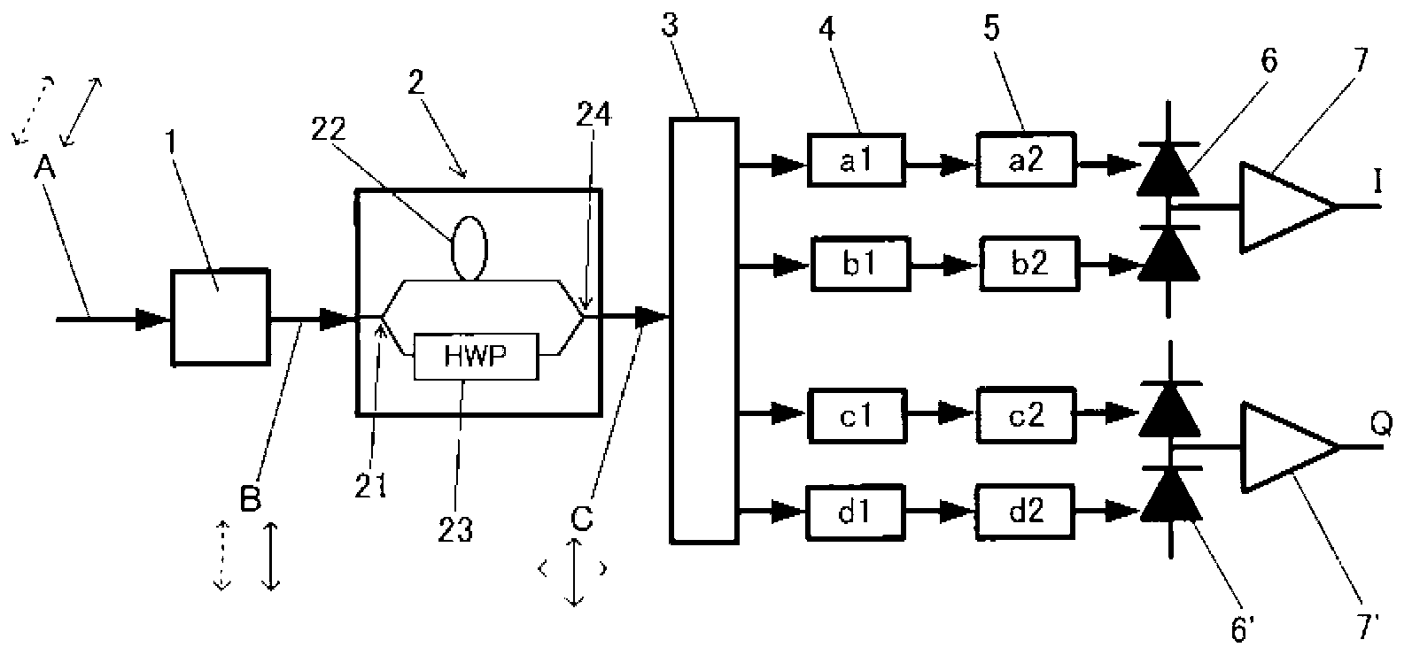
[0040] The invention is like figure 1 As shown, the optical receiver that demodulates the DQPSK modulated optical signal A into a multi-level phase modulation signal is characterized by including an interference unit 2 which branches the DQPSK modulated optical signal into two, Delay at least one of the branched lights so that the two branched lights have a predetermined phase difference, and rotate the polarization plane of at least one of the branched lights so that the polarization planes of the two branched lights become orthogonal, and then make the two branched lights Perform multiplexing; split-wave adjustment unit (3~5), which splits the output light from the interference unit and adjusts the polarization surface of the split-wave light; detection unit 6, 6', which detects from the split-wave adjustment unit Each light intensity of the output demultiplexed light; the optical ...


PUM


Abstract

Provided is a light receiver which demodulates an optical signal modulated by DQPSK to a multi-level phase modulation signal, wherein demodulation can be performed by using one interferometer. In a light receiver which demodulates an optical signal (A) modulated by DQPSK to a multi-level phase modulation signal, the optical signal modulated by DQPSK is branched into two, one of the branched lights is delayed so that the two branched lights have a predetermined phase difference, and a polarization plane of at least one of the branched lights is rotated so that polarization planes of the two branched lights are orthogonal to each other, and thereafter, an interference means (2) combines the two branched lights, branch adjusting means (3 to 5) branch the output light from the interference means and adjust the polarization surfaces of the branched lights, detection means (6, 6'); detect light intensity of each branched light output from the branch adjusting means, and an I (In-phase) component signal and a Q (Quadrature) component signal are generated on the basis of each detection signal of the detection means.

Description

Technical field [0001] The present invention relates to an optical receiver, in particular to an optical receiver that demodulates a DQPSK modulated optical signal into a multi-level phase modulation signal. Background technique [0002] With the increase in communication transmission volume, the introduction of multi-value modulation and demodulation coding technology has been discussed in the next-generation long-distance and large-capacity optical communication system pursuing high-speed and large-capacity. One of the representative methods is the differential quadrature phase shift keying (DQPSK modulation, Differential Quadrature Phase Shift keying) method. In this method, compared with the conventional binary intensity modulation (OOK) method, the signal band is narrower, the frequency utilization efficiency can be improved and the transmission distance can be expanded, and higher sensitivity can be expected. [0003] First of all, the quadrature phase shift keying (QPSK mod...

Claims


Application Information

Patent Timeline
Patent Type & Authority Applications(China)
IPC IPC(8): H04B10/04H04B10/06H04B10/14H04B10/142H04B10/152H04B10/26H04B10/28H04B10/67
CPCH04B10/677
Inventor 牟礼胜仁日隈薰片冈利夫宫崎德一宫地正英及川阳一志贺代康长枝浩
Owner SUMITOMO OSAKA CEMENT CO LTD
Why Eureka
Try Eureka