Easily soldered shield case for electromagnetic-wave shielding

A technology for shielding shells and electromagnetic waves, which is applied in the fields of magnetic/electric field shielding, electrical components, casings/cabinets/drawer components, etc. It can solve the problems of changing stamping dies, inconvenient re-operation, poor thermal conductivity, etc., and achieves Less movement and deflection, good productivity, and high heat transfer efficiency

Inactive Publication Date: 2012-10-17
JOINSET
View PDF6 Cites 15 Cited by
  • Summary
  • Abstract
  • Description
  • Claims
  • Application Information

AI Technical Summary

Problems solved by technology

[0012] According to this technology, compared with the shield case using metal foil, the injection molding of the insulating heat-resistant polymer with holes formed is thicker, so the application to small-sized products such as mobile devices will be limited, and surface modification is required. metal treatment and therefore has the disadvantage of being expensive
Moreover, it has the disadvantage of being very inconvenient to install injection molded objects with holes on the ball-shaped solder previously installed on the printed circuit board.
In particular, it has the disadvantages of inconvenient rework and poor thermal conductivity
[0013] In addition, the existing shielding case for electromagnetic wave shielding is produced by continuous punching processing of a metal sheet having a strength above a certain strength, such as stainless steel. The position is also changed, so there is a problem that the stamping die needs to be changed accordingly

Method used


Image

  • Easily soldered shield case for electromagnetic-wave shielding
  • Easily soldered shield case for electromagnetic-wave shielding
  • Easily soldered shield case for electromagnetic-wave shielding

Examples


Embodiment Construction

[0072] Hereinafter, embodiments of the present invention will be described in detail with reference to the accompanying drawings.

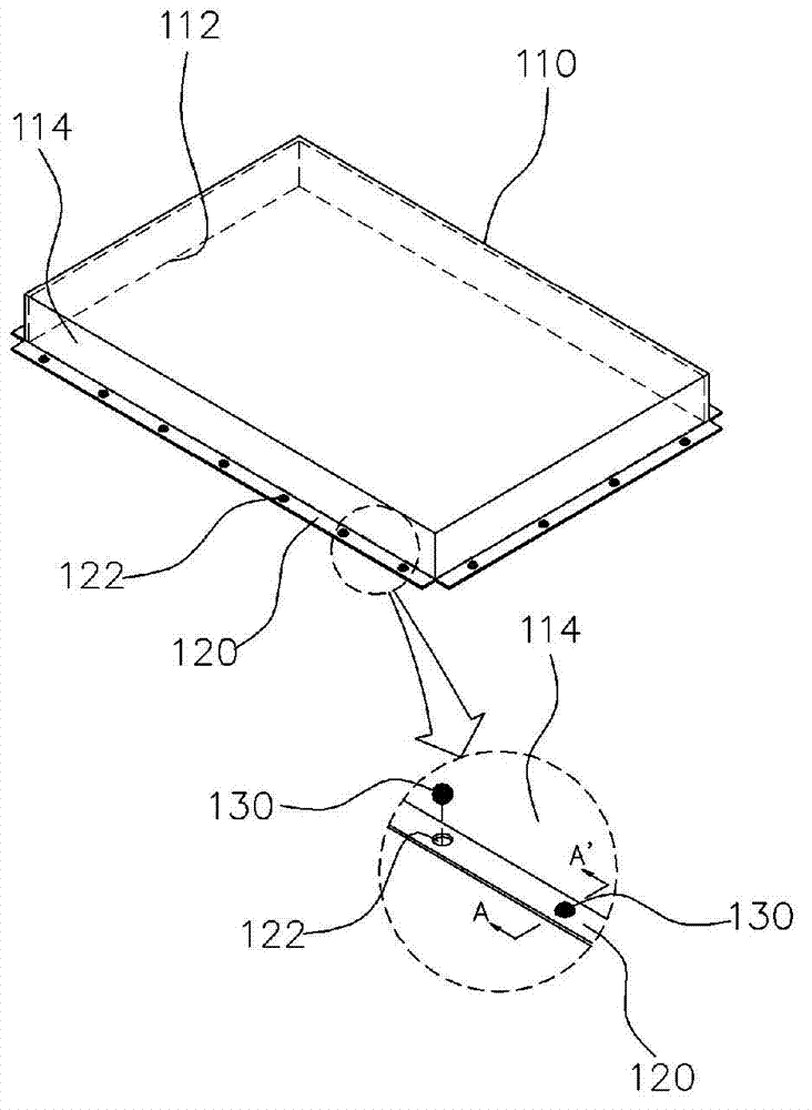
[0073] figure 2 An easily weldable shielding case 100 for electromagnetic wave shielding provided by an embodiment of the present invention is shown.

[0074] The shielding case 100 for electromagnetic wave shielding provided in this embodiment includes: a box-shaped metal body 110 with one side (the lower side in this embodiment) open and having conductivity; extending toward the outside or inside along the edge of the opening 112 of the body 110 , and a flange 120 integrally formed with the edge of the opening 112; a plurality of through holes 122 formed along the flange 120;

[0075] According to this structure, after the vacuum pick-up on the main body 110 of the shielding case 100, the inner surface of the flange 120 is mounted on the solder paste or flux of the ground pattern of the printed circuit board, and the solder part 130 and the gr...


PUM


Abstract

Disclosed is an easily soldered shield case for electromagnetic-wave shielding. The shield case comprises: a metal main body in the shape of a box of which the bottom surface is open; a flange which is formed extending integrally outward or inward from the open edge of the main body; a plurality of through holes formed along the flange or a plurality of recesses formed along the rear surface of the flange; and a solder member which is stably placed on the through holes or the recesses and projects in the thickness direction of the flange, wherein the shield case is mounted on a printed circuit board and the solder member is electrically and mechanically joined to the printed circuit board by means of soldering.

Description

technical field [0001] The present invention relates to a shield case for electromagnetic wave shielding, and in particular to a shield case for electromagnetic wave shielding soldered to a ground pattern of a printed circuit board. Furthermore, it also relates to the shielding case for electromagnetic wave shielding which can realize surface mount by vacuum pick-up and reflow soldering, has high productivity, and is easy to rework. Background technique [0002] Generally, in order to prevent electromagnetic waves generated in high-frequency electronic components or modules from propagating to the outside, or to protect these high-frequency electronic components or modules from interference from electromagnetic waves generated outside, these high-frequency components are covered with shielding cases for electromagnetic wave shielding. After the high-frequency components or modules, the shielding case for electromagnetic wave shielding is electrically and structurally connect...

Claims


Application Information

Patent Timeline
Patent Type & Authority Applications(China)
IPC IPC(8): H05K9/00
CPCH05K9/0028H05K9/0032H05K9/00H05K5/02
Inventor 金善基
Owner JOINSET
Why Eureka
Try Eureka