
Multipurpose waveband pressure wave device for metal honeycomb carrier

A metal honeycomb carrier and wave band technology, which is applied in the field of metal honeycomb carrier processing equipment, can solve the problems of unsatisfactory, single pressing structure, unsatisfactory pressure wave height, etc., to ensure product quality, reduce waste amount, and reasonable structure design. Effect

Inactive Publication Date: 2012-10-24
浙江欧信环保科技有限公司
View PDF11 Cites 4 Cited by
  • Summary
  • Abstract
  • Description
  • Claims
  • Application Information

AI Technical Summary

Problems solved by technology

The outermost part of the catalytic converter is a stainless steel shell, and its interior is a catalyst carrier; with the development of society, the shape of the catalyst carrier is also constantly changing, and its shape develops from layered, spiral, cross-shaped to the commonly used S Shape and SM shape, more effectively distribute the tension and thermal expansion deformation, improve durability, and the inner cores of various shapes are made of metal corrugated tape, currently in the process of processing metal corrugated tape, Its pressing structure is single, and the same equipment cannot meet the processing requirements of different corrugations, especially the requirements of different corrugated wave heights for the same corrugated belt, and cracks or deformations will appear on the edges of the initial section and the end section during rolling. , it cannot meet the change of the mesh number of the carrier from the center to the surrounding, which affects the product quality, and the amount of waste is large, which cannot meet the use requirements

Method used


Image

  • Multipurpose waveband pressure wave device for metal honeycomb carrier

Examples


Embodiment Construction

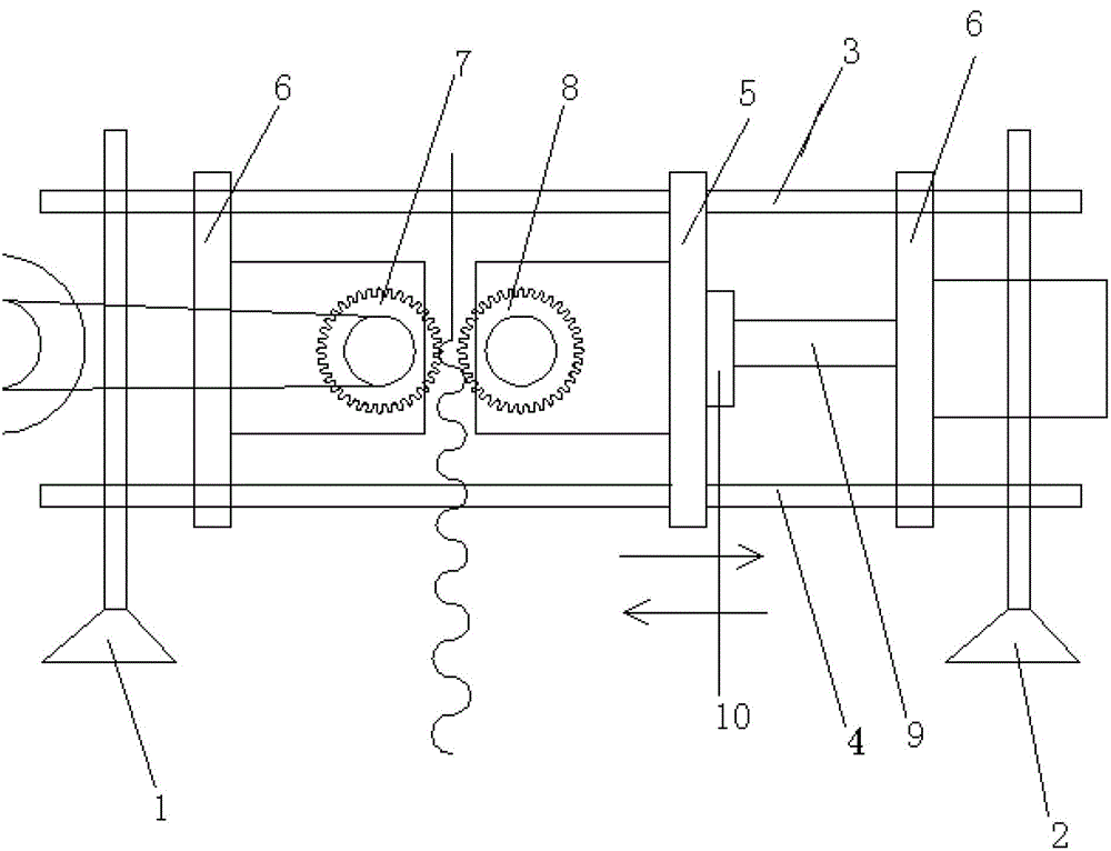
[0012] Referring to the accompanying drawings, a multi-purpose metal honeycomb carrier corrugated wave compression device includes left and right fixing frames 1, 2, and upper and lower guide rods 3, 4 are respectively arranged between the left and right fixing frames 1, 2 , between the upper and lower guide rods 3,4 is slidingly fitted with a slide plate 5, a fixed plate is fixedly installed between the slide plate 5 and the left and right fixed brackets 1, 2 respectively, and the fixed plate 6 on the left side and the slide plate 5 are respectively rotated and installed There are corresponding active pressure wave rollers 7 and driven pressure wave rollers 8. The rotation of the active pressure wave rollers 7 is driven by a motor, and the movement of the driven pressure wave rollers 8 is driven by a motor and a screw. The screw mandrel 9 is equipped with The screw nut 10 is fixedly connected to the outside of the slide plate 5; the teeth of the active pressure wave roller 7 a...


PUM


Abstract

The invention discloses a multipurpose waveband pressure wave device for a metal honeycomb carrier. The multipurpose waveband pressure wave device comprises a left fixing frame and a right fixing frame, an upper guide rod and a lower guide rod are respectively arranged between the left fixing frame and the right fixing frame, a sliding plate is slidably matched between the upper guide rod and the lower guide rod, fixing plates are respectively fixedly installed between the sliding plate and the left fixing frame and between the sliding plate and the right fixing frame, a driving pressure wave rolling wheel and a driven pressure wave rolling wheel which are corresponding are rotatably installed on the fixing plate on the left side and the sliding plate respectively, the driving pressure wave rolling wheel is driven by a motor to rotate, the driven pressure wave rolling wheel is driven by the motor and a screw rod to move, and a screw rod nut is installed on the screw rod in a matched mode and fixedly connected with the outer side of the sliding plate. The multipurpose waveband pressure wave device is reasonable in structure design and meets the requirements of an identical corrugated belt for different pressure wave heights, cracking or deformation and the like cannot occur in shrunk edges of an initial section and a terminate section in pressing simultaneously, product quality is guaranteed, and waste material quantity is reduced.

Description

technical field [0001] The invention relates to the field of metal honeycomb carrier processing equipment, in particular to a multi-purpose metal honeycomb carrier corrugated wave pressing device. Background technique [0002] The automotive catalytic converter is an engine external purification device that can purify carbon monoxide (CO), hydrocarbons (HC), hydrocarbons (HC) and nitrogen oxides (NO) emitted from the vehicle. A catalytic converter that can only purify CO and HC is an oxidation catalytic converter; a catalytic converter that can purify CO, HC and NO that pollutes the environment is a three-way catalytic converter. The outermost part of the catalytic converter is a stainless steel shell, and its interior is a catalyst carrier; with the development of society, the shape of the catalyst carrier is also constantly changing, and its shape develops from layered, spiral, cross-shaped to the commonly used S Shape and SM shape, more effectively distribute the tension...

Claims


Application Information

Patent Timeline
Patent Type & Authority Applications(China)
IPC IPC(8): B21D13/04
Inventor 丁胜康
Owner 浙江欧信环保科技有限公司
Learn More