
Air cooling electric spindle device for precision numerical control lathe

A technology of precision numerical control and electric spindle, applied in metal processing machinery parts, maintenance and safety accessories, metal processing equipment, etc., can solve the problems of excessively long transmission chain, small transmission torque, poor working accuracy, etc., to achieve simple and compact structure, The effect of avoiding liquid leakage and improving the service life

Active Publication Date: 2015-02-04
ZHEJIANG RIFA PRECISION MACHINERY
View PDF6 Cites 0 Cited by
  • Summary
  • Abstract
  • Description
  • Claims
  • Application Information

AI Technical Summary

Problems solved by technology

[0003] The purpose of the present invention is to overcome the shortcomings of the existing lathe spindle structure, such as too long drive chain, large external dimensions, small transmission torque, poor working accuracy, poor spindle rotation positioning, and poor heat dissipation of the spindle. The present invention provides a high-precision, Accurate positioning, good heat dissipation, precision CNC lathe air-cooled electric spindle device

Method used


Image

  • Air cooling electric spindle device for precision numerical control lathe
  • Air cooling electric spindle device for precision numerical control lathe
  • Air cooling electric spindle device for precision numerical control lathe

Examples


Embodiment Construction

[0019] Specific embodiments of the present invention will be described in detail below in conjunction with the accompanying drawings.

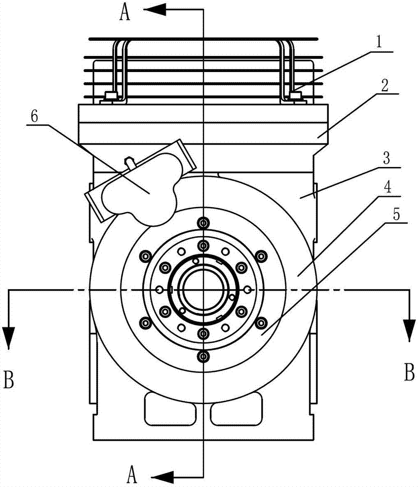
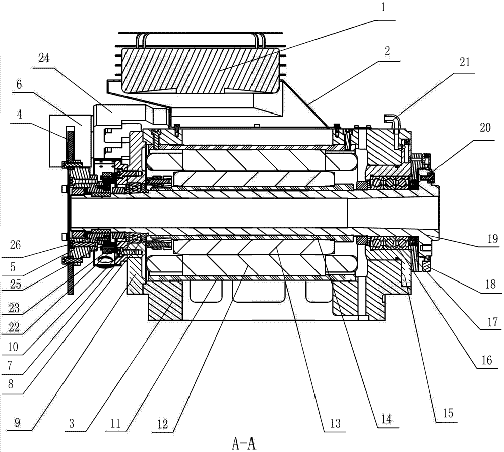
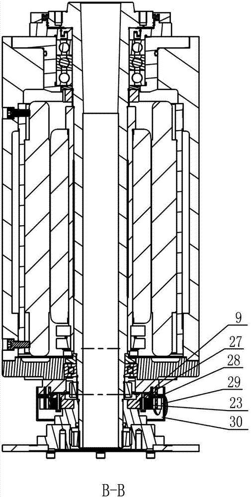
[0020] like Figure 1~Figure 3 As shown, the present invention includes a main shaft housing 3, a front bearing support 15, a rear bearing support 9, a hollow main shaft 19, a main shaft driving mechanism, an angle encoder device, a braking device and a cooling system, and the main shaft housing 3 is provided with a main shaft The hole and air pipe joint 21, the front bearing support 15 and the rear bearing support 9 are installed on the front and rear ends of the main shaft hole respectively, and the front and rear bearing supports are all provided with axial through holes, axial through holes and main shaft holes Concentric, the main shaft 19 is installed in the main shaft hole, the front end of the main shaft 19 is installed on the axial through hole of the front bearing support 15 through the angular contact ball bearing 16, the front bear...


PUM


Abstract

The invention relates to an air cooling electric spindle device for a precision numerical control lathe and belongs to the field of a part device of a machine tool. The existing lathe spindle has complex structure, poor accuracy and poor heat dissipation. The air cooling electric spindle device for the precision numerical control lathe comprises a spindle box body, a front bearing support, a rear bearing support, a hollow spindle, a spindle driving mechanism, an angle coder device, a brake device and a cooling system; the hollow spindle is supported and arranged on the front and rear bearing supports at both ends of a spindle hole of the spindle box body by bearings; the spindle is driven by the spindle driving mechanism to rotate; the angle coder device is arranged at the rear end of the spindle by a connecting sleeve; the brake device comprises a brake disk and a hydraulic brake; the hydraulic brake is arranged at the rear end of the spindle box body by a bracket; the brake disk is arranged at the rear end of the connecting sleeve; the cooling device comprises a fan and the bracket; the fan is arranged on the spindle box body by the bracket; and the fan is over against a vent on the spindle box body. The spindle, an angle coder and the cooling of the fan are braked by the brake device; the processing and positioning accuracy of the electric spindle is improved; and the heat dissipation is also good.

Description

technical field [0001] The invention belongs to a machine tool component device, in particular to an electric spindle device for a precision numerical control lathe. Background technique [0002] At present, the transmission chain of the ordinary lathe spindle structure is too long, the external dimension is large, and the transmission torque is small, which affects the transmission accuracy and positioning accuracy of the lathe spindle, and when it is necessary to stop processing, the spindle cannot stop immediately, and the control is poor; High-speed rotation, so water-cooling is generally used for cooling. There is a risk of liquid leakage in water-cooling, which affects environmental sanitation. The existing technology also uses air-cooled electric spindles, but the fans are installed at the rear end of the spindle, which affects the increase in spindle speed and heat dissipation. The effect is not ideal. Contents of the invention [0003] The purpose of the pres...

Claims


Application Information

Patent Timeline
Patent Type & Authority Patents(China)
IPC IPC(8): B23B19/02B23B19/00B23Q11/12
Inventor 聂志亭陆平山周德润任正法
Owner ZHEJIANG RIFA PRECISION MACHINERY
Learn More