Welding assisting device

A technology for auxiliary devices and welding parts, applied in auxiliary devices, welding equipment, manufacturing tools, etc., can solve the problems of tin-to-tin, pin short-circuit, etc., to prevent chip short-circuit and increase the effect of adhesion surface

Inactive Publication Date: 2012-10-24
HONG FU JIN PRECISION IND (SHENZHEN) CO LTD +1
View PDF7 Cites 0 Cited by
  • Summary
  • Abstract
  • Description
  • Claims
  • Application Information

AI Technical Summary

Problems solved by technology

However, when soldering the last few pins, the tension between the tin and the soldering iron is less than the tension between the tin and the pins due to the smaller contact area between the tin on the soldering iron and the pins, so that excess solder will remain on the last few pins. The tin produces a tin connection problem, resulting in a short circuit of the pin

Method used


Image

  • Welding assisting device
  • Welding assisting device
  • Welding assisting device

Examples


Embodiment Construction

[0013] The present invention will be further described in detail below in conjunction with the accompanying drawings.

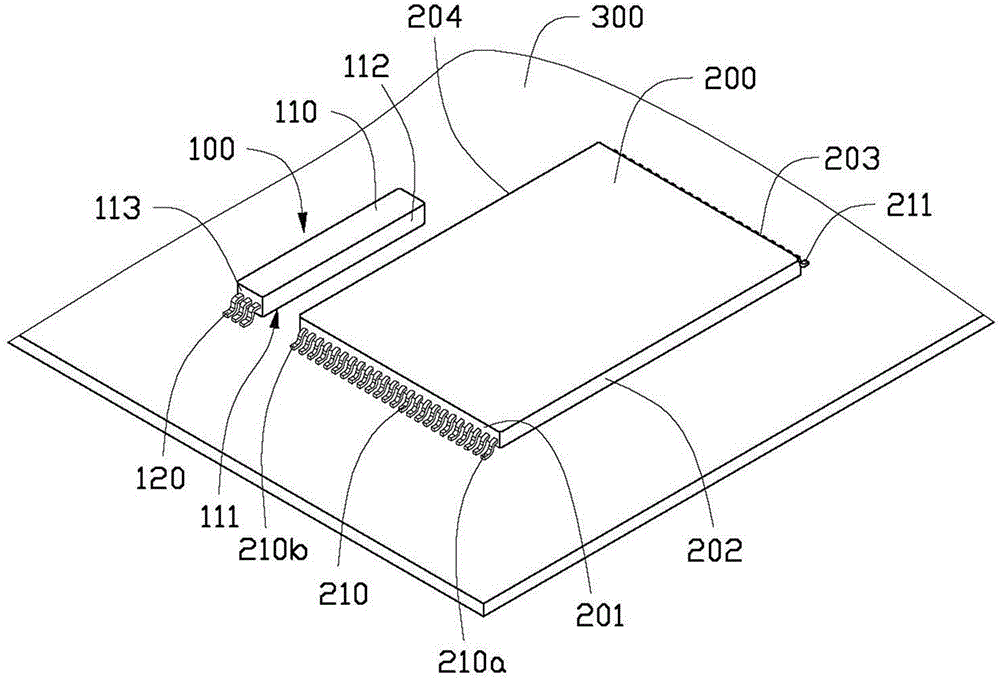
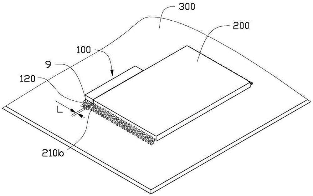
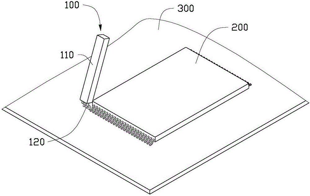
[0014] see figure 1 , the welding auxiliary device 100 provided by the present invention. During the auxiliary soldering process, the soldering auxiliary device 100 is disposed on one side of a chip 200 . The chip 200 includes a first side 201 , a second side 202 , a third side 203 and a fourth side 204 connected end to end. The first row of pins 210 and the second row of pins 211 are respectively fixed on the first side 201 and the third side 203 . The first row of pins 210 includes outer pins 210a, 210b located at two ends of the first side 201 .

[0015] During the soldering process, the soldering auxiliary device 100 is also placed on the circuit board 300, located on the side of the outer pin 210a or 210b of the chip 200, and then the chip 200 is fixed on the circuit board by using tin pulling technology. 300 on. In this embodiment, welding is perfo...


PUM


Abstract

The invention provides a welding assisting device which is used for providing assistance in welding a chip, wherein a row of pins is arranged on one side of the chip, including the outside pin positioned at one end of the side. The welding assisting device comprises a fixed part and a welding part, wherein the welding part is made of a material having high tin adhering performance; the welding part is connected with the fixed part; and the welding part is adjacent to the outside pin; and the space between the welding part and the outside pin is not greater than twice the space between the adjacent pins of the chip. According to the welding assisting device, the welding part is arranged adjacent to the outermost pin of the chip, and the attaching face of welded tin is added when a welding iron is shifted to the outermost pin, thus, the welded tin can be attracted on the welding part and finally remained on the welding part of the welding assisting device, as a result, the welded tin remained between the outside pin of the chip and the pin on the chip adjacent to the outside pin can be avoided; and the chip can be prevented from short circuit.

Description

technical field [0001] The invention relates to a welding auxiliary device. Background technique [0002] When the existing multi-pin chip is manually soldered, the drag soldering technique is often used. The drag soldering technology is to hang a little solder on the blade of the soldering iron during soldering, and drag the blade along a row of chip pins from one end to the other side slowly, forming uniform solder joints on each pin at one time. However, the initial tension between the pin and the tin is less than the tension between the soldering iron and the tin, and the excess tin can be smoothly detached from the surface of the pin. However, when soldering the last few pins, the tension between the tin and the soldering iron is less than the tension between the tin and the pins due to the smaller contact area between the tin on the soldering iron and the pins, so that excess solder will remain on the last few pins. The tin produced the problem of tin connection, res...

Claims


Application Information

Patent Timeline
Patent Type & Authority Applications(China)
IPC IPC(8): B23K3/08
CPCB23K1/0016B23K3/08
Inventor 潘爱裕王金有赖超荣
Owner HONG FU JIN PRECISION IND (SHENZHEN) CO LTD
Why Eureka
Try Eureka