Method for inserting generator rotor of gas-filling condensing steam turbine unit

A technology for generator rotors and steam turbine units, applied in metal processing, metal processing equipment, manufacturing tools, etc., can solve the problems of scratching stator safety accidents, affecting construction progress and maintenance quality, and reducing maintenance efficiency, and achieving good social benefits. And economic benefits, easy to grasp the essentials of operation, saving construction costs

Inactive Publication Date: 2012-10-24
ANGANG CONSTR CONSORTIUM
View PDF6 Cites 8 Cited by
  • Summary
  • Abstract
  • Description
  • Claims
  • Application Information

AI Technical Summary

Problems solved by technology

The disadvantage of this dressing method is that the arc-shaped slide plate must be installed in the stator core first, and the arc-shaped slide plate must be removed after the dressing, which is complicated to operate; The pull hoist works, which reduces the maintenance efficiency, the labor intensity is high, and the safety accident of scratching the stator is prone to occur, which affects the construction progress and maintenance quality

Method used


Image

  • Method for inserting generator rotor of gas-filling condensing steam turbine unit
  • Method for inserting generator rotor of gas-filling condensing steam turbine unit
  • Method for inserting generator rotor of gas-filling condensing steam turbine unit

Examples


Embodiment Construction

[0021] The specific embodiment of the present invention will be further described below in conjunction with accompanying drawing:

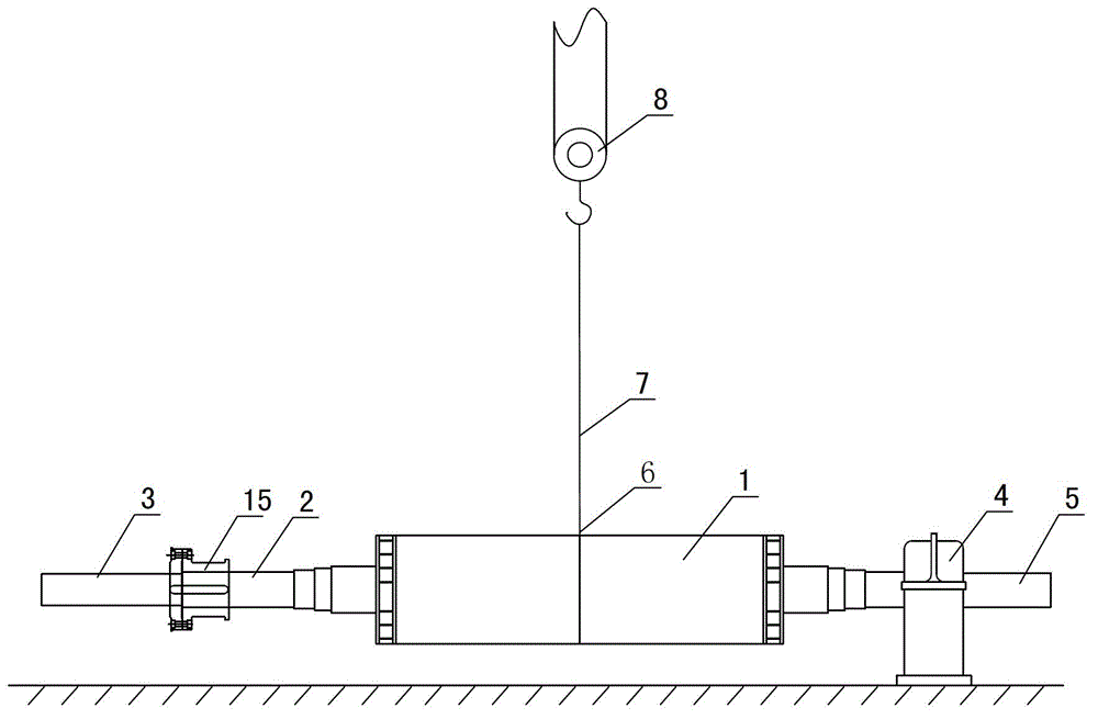
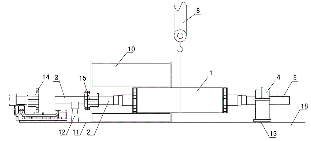
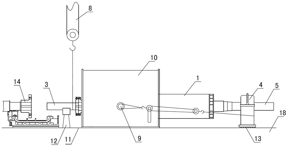
[0022] The present invention relates to a method for putting on the generator rotor of a gas-supplying condensing steam turbine unit, which is to change the position of the center of mass of the rotor 1 by arranging a connecting shaft at the steam end 2 of the generator rotor and connecting the counterweight to the exciter end 5 to change the position of the rotor 1 The rotor is more convenient to put on and install. The specific operation steps are as follows:

[0023] 1) see figure 1 , connect the connecting shaft 3 with the steam end coupling 15 of the rotor 1, hang the rear bearing seat 4 on the journal of the exciter end 5 as a counterweight, determine and mark the hoisting center 6 of the rotor 1, the exciter end 5 A soft pad should be provided between the journal and the rear bearing seat 4 of the generator to prevent the rear bearing seat...


PUM


Abstract

The invention relates to the field of steam turbine units, and in particular relates to a method for inserting a generator rotor of a gas-filling condensing steam turbine unit. The method is characterized in that a connecting shaft is arranged at the steam end of the generator rotor and a balance weight is hanged at the exciter end. The method comprises the operation steps of: (1), connecting the connecting shaft with the steam end of the generator rotor, and hanging a rear bearing base of a generator on a shaft neck of the exciter to be used as the balance weight; (2), lifting the rotor to be in a horizontal state; (3) slowing inserting the steam end into a stator; (4) moving a lifting point to the root part of the connecting shaft until the connecting shaft end is close to a back wheel of the steam turbine; (5) moving the lifting point to the steam end of the rotor; (6), continuously drafting the rotor by using a chain block until a shaft coupler at the steam end is close to the back wheel, and connecting the steam end with the back wheel of the steam turbine; and (7) rotating the rotor after the rotor is in position. Compared with the prior art, the method has the beneficial effects of stability, efficiency, safety, good social benefit and economic benefit; and moreover, the operation skills are easy to manage.

Description

technical field [0001] The invention relates to the maintenance field of an air-supply and condensing steam turbine unit, in particular to a method for putting on a generator rotor of an air-supply and condensing steam turbine unit. Background technique [0002] At present, in the installation and maintenance of the air-supplementing and condensing steam turbine units at home and abroad, most of the slides are installed in the stator to pass through the rotor, that is, when the generator rotor is installed, an arc-shaped slide is laid in the stator core. Put the slider device on the arc-shaped slide plate, first use the crane to lift the rotor, put the front part of the rotor into the stator, put down the rotor so that the center of gravity of the front part of the rotor falls on the arc-shaped slide plate inside the stator, and the rear part is supported by the sleeper. Move the sling of the crane to the tail of the rotor, lift the rotor, and then use the hand chain hoist i...

Claims


Application Information

Patent Timeline
Patent Type & Authority Applications(China)
IPC IPC(8): B23P19/00
Inventor 王琦徐世红武振海杨配良龚强
Owner ANGANG CONSTR CONSORTIUM
Why Eureka
Try Eureka