Device for winding web of material

A bearing device and web rolling technology, which is applied in the field of devices for winding material webs into rolls, can solve problems such as inability to achieve

Active Publication Date: 2012-10-24
VOITH PATENT GMBH
View PDF8 Cites 2 Cited by
  • Summary
  • Abstract
  • Description
  • Claims
  • Application Information

AI Technical Summary

Problems solved by technology

[0006] Attempts have been made so far to solve this problem by setting the first natural frequency of the s...

Method used


Image

  • Device for winding web of material
  • Device for winding web of material
  • Device for winding web of material

Examples


Embodiment Construction

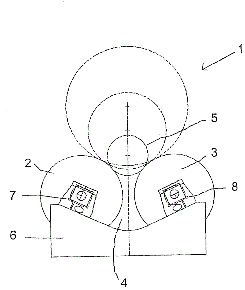
[0034] figure 1A winding device 1 is shown very schematically in the form of a double support roll winder. The winding device 1 has two support rollers 2, 3, between which a winding bed 4 is formed, in which a schematically shown mandrel 5 is arranged, onto which a not described in greater detail is wound. Material web. The structural arrangement of such a double backup roll winder is already known.

[0035] The two support rollers 2 , 3 are supported in a frame 6 . Each of the back-up rolls 2,3 has a bearing arrangement supported by a bearing 7,8 at each end of the back-up roll 2,3. Only bearings 7 and 8 are in figure 1 are visible separately.

[0036] This winding device can be operated at maximum conveying speed. The conveying speed is, for example, 2500 m / min or 3000 m / min. This results in a defined number of revolutions and thus a defined rotational frequency of the support rollers 2 , 3 . The winding device is designed for this rotational frequency. The number o...


PUM


Abstract

The present invention provides a device for winding a web of a material on a winding roll (5), comprising at least at least one roller (2, 3), wherein the roll abuts against the roller when winding and enables the roller to rotate when winding, the roller (2, 3) is supported in a bearing apparatus by bearings (7, 8) at end portion of each roller. It is also desired to wind the vibration-critical web of material with as fewer problems as possible. Therefore, it is determined that the bearings (7, 8) are provided with a liquid static pressure bearing with at least one first bearing oil chamber (12) supplied by a hydraulic liquid.

Description

technical field [0001] The invention relates to a device for winding a web of material into a roll, the device having at least one roller against which the roll rests during winding and which rotates during winding, wherein the roll is moved every The ends of each roller are supported by bearings in the bearing unit. Background technique [0002] The invention is illustrated below using a paper web as an example of a material web. However, it can also be used in the case of other material webs in which similar problems arise. The device for winding the web enables large working widths of more than 10 m. The reels produced on them can reach a final diameter of 1.6 m and more when the material web is divided longitudinally. The final diameter can be 3.5 m and larger without the material web being divided. [0003] When winding a paper web, it is always observed that the winding device is in vibration. This vibration is undesirable for a number of reasons. On the one hand...

Claims


Application Information

Patent Timeline
IPC IPC(8): B65H18/20
CPCB65H2601/524B65H2402/525B65H18/20B65H2402/52
Inventor R·范哈格
Owner VOITH PATENT GMBH
Why Eureka
Try Eureka