Hybrid drill bit

A technology of mixing drill bits and drill bit bodies, which is applied to drill bits, drilling equipment, earth-moving drilling, etc., can solve the problems of easy impact damage of cutting elements, slow ROP of diamond bits, and slow ROP of roller cone bits, etc. Eliminate stick-slip phenomenon, improve cutting efficiency and ROP, and smooth pre-crushing effect

Inactive Publication Date: 2012-10-24
SINOPEC OILFIELD EQUIP CORP
View PDF9 Cites 23 Cited by
  • Summary
  • Abstract
  • Description
  • Claims
  • Application Information

AI Technical Summary

Problems solved by technology

[0002] In the prior art, when the drilling encounters a hard formation, the commonly used PDC diamond bit mainly realizes downhole drilling through scraping movement, and the main cutting elements on the nose and shoulder of the diamond bit are difficult to effectively eat into the bottom of the well For rocks, the ROP of the diamond drill bit will become very slow; while the roller cone bit breaks the rock by impact crushing, which is easy to produce deep crushing tooth pits in the rock, but due to the hard formation, the rock cannot be broken by volume, so The cutting efficiency of the cutting teeth of the roller cone bit is also very low, and the drilling speed of the roller cone bit is also very slow
On the other hand, when the drill bit encounters some formations with more soft and hard interlayers, the cutting elements of the PDC diamond bit are extremely vulnerable to impact damage. In order to deal with this situation, Chinese patent document CN200880016630. A hybrid drill bit composed of diamond drill bits, although the hybrid drill bit has strong comprehensive performance, it has the following disadvantages: due to the rock-breaking mechanism of the tricone bit’s unique impact crushing, the impact load generated by the cone rotation is easy to cause the diamond The PDC composite sheet of the cutting element of the drill bit is broken, resulting in a decrease in the ROP of the drill bit

Method used


Image

  • Hybrid drill bit
  • Hybrid drill bit
  • Hybrid drill bit

Examples


Embodiment Construction

[0021] Further illustrate the embodiment of the patent of the present invention below in conjunction with accompanying drawing.

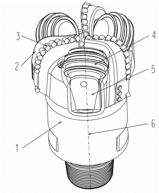
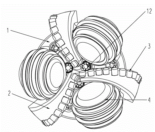
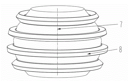
[0022] Including a bit body 1, three blades 2 are arranged on the bit body, cutting teeth are arranged on the inner cone, nose and shoulder of the blades 2, the cutting teeth are diamond composite sheets 3, and the bit body 1 is provided with cutting teeth. There are hydraulic injection holes, and nozzles 12 are fixed on each injection hole. Disc cones 4 are installed between the blades 2, and three blades are equipped with three disc cones 4, which are interlaced with each other; the disc cones are connected to the bit body through the palm 5, and the The upper end of the tooth palm 5 is welded into one body with the bit body 1, and the lower end of the tooth palm 5 is provided with a journal, on which the disc cone 4 is set and axially locked by steel balls. The surface of the disc cone is a spherical surface, the angle a between the rotation axi...


PUM


Abstract

The invention relates to a hybrid drill bit for petroleum, natural gas and geological drilling. The hybrid drill bit comprises a drill bit body, wherein a cutter wing and a roller cone are arranged on the drill bit body, cutting teeth are arranged on the cutter wing, the roller cone is connected with the drill bit body through a cone leg, and the hybrid drill bit is characterized in that the roller cone is a disk type roller cone. A cutting element on the disk type roller cone is shaped like a disk cutter or an intermittent disk cutter. The patent disclosed by the invention has the beneficial effects that, 1) the scraping motion of a diamond drill bit and the rolling motion of a disk type roller cone drill bit are combined for realizing precrushing at the bottom of a well, thereby ensuring that the diamond cutting teeth can effectively bite rock, eliminating the stick-slip phenomenon of the drill bit in some special formations and the probability of impact disrepair of a polycrystalline diamond compact (PDC) and improving the cutting efficiency and the mechanical drilling speed of the drill bit; and 2) the disk type roller cone can realize the precrushing of a rock layer at the bottom of the well more steadily, reduce the impact on the PDC, enhance the stability in drilling of the drill bit and enable the drill bit to realize faster and more stable drilling.

Description

technical field [0001] The patent of the present invention relates to a hybrid drill bit for oil, natural gas and geological well drilling, which is suitable for drilling in hard formations and interlayer formations. Background technique [0002] In the prior art, when the drilling encounters a hard formation, the commonly used PDC diamond bit mainly realizes downhole drilling through scraping movement, and the main cutting elements on the nose and shoulder of the diamond bit are difficult to effectively eat into the bottom of the well For rocks, the ROP of the diamond drill bit will become very slow; while the roller cone bit breaks the rock by impact crushing, which is easy to produce deep crushing tooth pits in the rock, but due to the hard formation, the rock cannot be broken by volume, so The cutting efficiency of the cutting teeth of the roller cone bit is also very low, and the drilling speed of the roller cone bit is also very slow. On the other hand, when the drill...

Claims


Application Information

Patent Timeline
Patent Type & Authority Applications(China)
IPC IPC(8): E21B10/16E21B10/12E21B10/50
Inventor 程永宋满华樊孝兵吴素婷石志明刘聪周悦辉
Owner SINOPEC OILFIELD EQUIP CORP
Why Eureka
Try Eureka