Driving-driven hybrid vibration isolator

A hybrid vibration isolator, active and passive technology, applied in the direction of spring/shock absorber, vibration suppression adjustment, non-rotational vibration suppression, etc., can solve the problems of easily damaged actuators, large amount of permanent magnets, and poor closure of magnetic circuits , to achieve the effect of convenient use, simple wiring, and effective attenuation of vibration energy transmission

Inactive Publication Date: 2012-10-24
NAVAL UNIV OF ENG PLA
9 Cites 36 Cited by

AI-Extracted Technical Summary

Problems solved by technology

[0005] The existing "Inertial Mass Vibration Isolation Device for Automotive Engines" (Patent No. 200920067893.6) and "Active Vibration Isolator" (Patent No.: 200610092560.X) use rubber The mass actuator is fixed on the vibration-isolated target with a single-point installation method to control the line spectrum vibration. Due to the low integration of the active and passive components, it has the disadvantages of large space occupation and poor adaptability
In "Inertial Mass Vibration Isolation Device for Automotive Engines" (Patent No. 200920067893.6), the inertial mass electromagnetic actuator uses a cylindrical permanent magnet to provide a permanent magnetic field. Inside the cylinder, the electromagnetic field and permanent magnetic field generated ...

Method used

Electromagnetic actuator 2 is integrated in airbag vibration isolator 1, can make compact structure; The heat that electromagnetic actuator coil 15 energizes produces is passed to airbag vibration isolator by cooling fin 16, iron core 9 and armature 8 1 on the metal upper cover plate 5 and lower cover plate 7, and then quickly diffuse into the outside air through the machine feet and base of the vibration-isolated equipment. The temperature sensor 12 in the lower cover plate 7 and the actuator coil 15 monitors the temperature near the lower cover plate 7 of the airbag vibration isolator and the temperature of the actuator coil 15 in real time to ensure the safe and reliable operation of the system.
In technique scheme, iron core 9 is mountain-shaped structure, and coil 15 is wound on the center post 9.1 of mountain-shaped iron core, and the top of center post 9.1 of mountain-shaped iron core is fixed with first permanent magnet 13, and mountain-shaped The tops of the two side columns 9.2 of the iron core are all fixed with the second permanent magnet 14, and the magnetic pole direction of the first permanent magnet 13 and the magnetic pole direction of the second permanent magnet 14 are opposite. This structure makes the electromagnetic field and the permanent magnetic field of the electromagnetic actuator 2 highly closed, has small magnetic flux leakage, and has high electric-force conversion efficiency. The above structure can form two closed permanent magnetic circuits on the left and right, and the closed permanent magnetic circuit on the left side is: the N pole of the permanent magnet in the middle column of the iron core-the armature 8-the left air gap-the S pole of the left permanent magnet-the left side Permanent magnet N pole-left column of iron core-core middle column-iron core middle column permanent magnet S pole-iron core middle column permanent magnet N pole. And when the current passes through the coil 15, two closed electromagnetic magnetic circuits on the left and the right will also be formed. When the winding direction of the coil 15 is determined, the direction of the electromagnetic circuit is only determined by the direction of the current, which can be determined according to the right-hand rule. When the direction of the electromagnetic magnetic circuit generated by the current is the same as that of the permanent magnet magnetic circuit, the magnetic field in the air gap 17 increases, and the attractive force between the iron core 9 and the armature 8 increases; otherwise, the magnetic field in the air gap 17 decreases. The attractive force between the iron core 9 and the armature 8 is also reduced, so inputting an alternating current to the coil 15 can drive the electromagnetic actuator 2 to generate an alternating output force, thereby completing the task of line spectrum vibration control.
The present invention has adopted parallel hybrid vibration isolation mode, and electromagnetic actuator 2 has non-contact characteristic and can not cause vibration short-circuit transmiss...

Abstract

The invention discloses a driving-driven hybrid vibration isolator which comprises an air bag vibration isolator, wherein the air bag vibration isolator comprises an upper cover plate, a lower cover plate and an elastic bag body arranged between the upper cover plate and the lower cover plate. An electromagnetic actuator is arranged in the elastic bag body and comprises an armature, an iron core matched with the armature and a coil winding on the iron core, the armature is fixed on the upper cover plate, the iron core is fixed on the lower cover plate, an air gap is reserved between the armature and the iron core, a radiating sheet is arranged on the coil, and the bottom of the radiating sheet is connected with the lower cover plate. An air hole and a line hole respectively leading to the elastic bag body are arranged on the lower cover plate, an air sealing socket is arranged at the outlet position of the line hole, and a vibration sensor connected with a work state control end of the electromagnetic actuator is arranged on the lower cover plate. The driving-driven hybrid vibration isolator has the advantages of being high in reliability, small in energy consumption, low in cost, small in occupied space, good in adaptability and the like, can be adjusted adaptatively along with load changing of a vibration isolating device, and can achieve synchronous and effective control of broadband vibration and line spectrum vibration.

Application Domain

Non-rotating vibration suppression

Technology Topic

BroadbandHeat sink +5

Image

  • Driving-driven hybrid vibration isolator
  • Driving-driven hybrid vibration isolator
  • Driving-driven hybrid vibration isolator

Examples

  • Experimental program(1)

Example Embodiment

[0030] The present invention will be further described in detail below in conjunction with the drawings and specific embodiments:
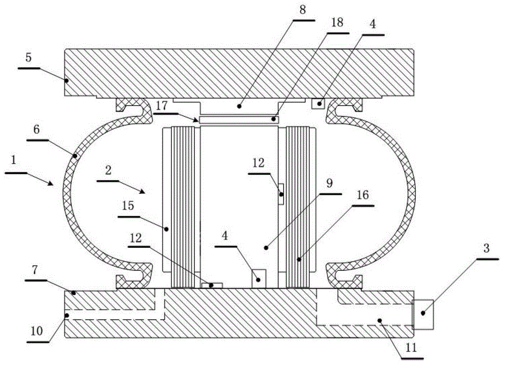
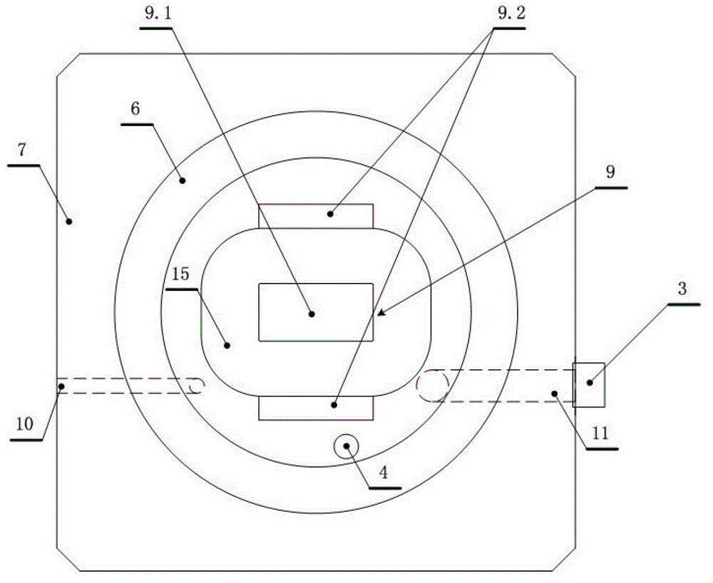
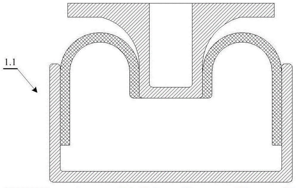
[0031] The active and passive hybrid vibration isolators shown in 1 to 4 in the figure include airbag vibration isolator 1. The airbag vibration isolator 1 includes an upper cover plate 5, a lower cover plate 7, and is arranged between the upper cover plate 5 and the lower cover plate 7. An electromagnetic actuator 2 is provided in the elastic capsule 6 between the elastic capsule 6 and the electromagnetic actuator 2 includes an armature 8, an iron core 9 matched with the armature 8, and a coil 15 wound on the iron core 9, in which, The armature 8 is fixed on the bottom of the upper cover plate 5, the iron core 9 is fixed on the top of the lower cover plate 7, there is an air gap 17 between the armature 8 and the iron core 9, the coil 15 is provided with a heat sink 16, and the bottom of the heat sink 16 is connected The lower cover 7 and the lower cover 7 are respectively provided with an air hole 10 and a wire hole 11 leading to the elastic capsule 6; the outlet of the wire hole 11 is provided with an airtight socket 3, and the lower cover 7 is provided with an electromagnetic operation The working state of the actuator 2 controls the vibration sensor 4 connected to the end.
[0032] In the above technical solution, the upper cover 5 may also be provided with a vibration sensor 4 connected to the working state control end of the electromagnetic actuator 2.
[0033] The above-mentioned airbag vibration isolator 1 relies on the air in the elastic bag body 6 to carry the weight, and has the advantages of light weight and good vibration isolation effect.
[0034] In the above technical solution, the coil 15 is connected to the working state control terminal of the electromagnetic actuator 2 through a power amplifier. The operating state control end of the electromagnetic actuator 2 detects the vibration signal of the lower cover plate 7 measured by the vibration sensor 4, generates an output signal according to the adaptive control algorithm, and drives the electromagnetic actuator 2 through the power amplifier, and then Realize line spectrum vibration control.
[0035] In the above technical solution, the sensitive axis of the vibration sensor 4 is parallel to the axis of the electromagnetic actuator 2, and the vibration sensor 4 may be an acceleration sensor or a speed sensor.
[0036] In the above technical solution, both the lower cover 7 and the coil 15 are provided with a temperature sensor 12, and the temperature sensor 12 is connected to the working state control end of the electromagnetic actuator 2.
[0037] In the above technical solution, the wires of the temperature sensor 12, the vibration sensor 4 and the electromagnetic actuator 2 are led out through the wire hole 11 and the airtight socket 3.
[0038] In the above technical solution, the iron core 9 has a mountain-shaped structure, the coil 15 is wound on the center column 9.1 of the mountain-shaped iron core, and the top of the center column 9.1 of the mountain-shaped iron core is fixed with the first permanent magnet 13, and the mountain-shaped iron core The tops of the two side posts 9.2 both fix the second permanent magnet 14, and the magnetic pole direction of the first permanent magnet 13 and the magnetic pole direction of the second permanent magnet 14 are opposite. This structure enables the electromagnetic field and the permanent magnetic field of the electromagnetic actuator 2 to have a high degree of closure, small magnetic leakage, and high electrical-force conversion efficiency. The above structure can form two closed permanent magnetic circuits on the left and right, of which the closed permanent magnetic circuit on the left is: iron core central column permanent magnet N pole-armature 8-left air gap-left permanent magnet S pole-left Permanent magnet N pole-iron core left column-iron core center column-iron core center column permanent magnet S pole-iron core center column permanent magnet N pole. When current passes through the coil 15, two closed electromagnetic magnetic circuits on the left and right are also formed. When the winding direction of the coil 15 is determined, the direction of the electromagnetic circuit is determined only by the direction of the current, which can be determined according to the right-hand rule. When the electromagnetic magnetic circuit generated by the current is in the same direction as the permanent magnetic circuit, the magnetic field in the air gap 17 increases, and the attractive force between the iron core 9 and the armature 8 increases, and vice versa, the magnetic field in the air gap 17 decreases. The attractive force between the iron core 9 and the armature 8 is also reduced. Therefore, inputting an alternating current to the coil 15 can drive the electromagnetic actuator 2 to generate an alternating output force, thereby completing the task of line spectrum vibration control.
[0039] In the above technical solution, the air bag vibration isolator 1 is a bag type air bag vibration isolator or a membrane type air bag vibration isolator 1.1.
[0040] In the above technical solution, the armature 8 and the iron core 9 are laminated by a plurality of silicon steel sheets with a thickness of 0.3 to 0.4 mm, preferably 0.35 mm silicon steel sheets. This can reduce eddy current loss.
[0041] In the above technical solution, the flexible magnetic conductive rubber 18 is filled in the air gap 17. The flexible magnetic conductive rubber 18 can reduce the magnetic resistance of the air gap, further improve the efficiency of electric-force conversion, reduce the power consumption of the actuator, and can also prevent the armature 8 and the iron core 9 from colliding.
[0042] In the above technical solution, the upper cover plate 5 and the lower cover plate 7 are both metal cover plates, and the metal cover plates are used to cooperate with the heat sink 16 to dissipate heat.
[0043] The invention is installed between the equipment and the base, and the airbag vibration isolator 1 carries the weight of the equipment and reduces the transmission of broadband vibration of the equipment to the base. The vibration sensor 4 outputs a signal related to the vibration of the equipment base and provides it to the working state control terminal. The working state control terminal generates a corresponding signal to change the current of the actuator coil 15 so that the actuator outputs a corresponding force to counteract the equipment base. The line spectrum of the seat is vibrating.
[0044] The miniaturization, non-contact, high energy efficiency, and low calorific value of the electromagnetic actuator of the present invention are the basis for integration into the airbag vibration isolator.
[0045] The heat generated by the electromagnetic actuator 2 should be quickly discharged through the heat dissipation device to ensure the safety, reliability and posture maintenance of the active and passive hybrid vibration isolator. In the present invention, the heat sink 16 is used to improve the heat dissipation efficiency of the actuator, and a heat pipe can also be used to replace the heat sink 16.
[0046] The electromagnetic actuator 2 and the vibration sensor 4 are integrated inside the airbag vibration isolator to realize vibration monitoring and control, and the temperature sensor 12 is integrated to ensure the safety and reliability monitoring of the active and passive hybrid vibration isolator. Therefore, the active and passive hybrid vibration isolator of this patent is a whole that combines vibration monitoring, control and reliability monitoring.
[0047] A wire hole 11 is opened on the cover of the airbag vibration isolator 1, and an airtight socket 3 is welded. The wires of the electromagnetic actuator 2, the vibration sensor 4 and the temperature sensor 12 are connected to the airtight socket 3, and are connected to the external power supply, monitoring and The control system is in contact, and at the same time, the air-tightness of the airbag isolator 1 can be maintained, so that the airbag isolator 1 can normally perform broadband vibration isolation and support the load of the equipment.
[0048] The working principle of the present invention is:
[0049] The present invention is installed between the equipment and the base, the upper cover 5 of the airbag vibration isolator is connected with the vibration isolation equipment, and the lower cover 7 is connected with the base.
[0050] The invention adopts the parallel hybrid vibration isolation mode, the electromagnetic actuator 2 has non-contact characteristics and will not cause vibration short-circuit transmission, so the vibration isolation effect of the airbag vibration isolator 1 is fully exerted, and it has an excellent broadband vibration isolation effect. The required active control force is relatively low; the present invention uses the airbag vibration isolator 1 to support the equipment load, and the electromagnetic actuator 2 does not need to provide static support force. Compared with other types of actuators commonly used in series vibration isolation mode, it has a smaller power Consumption and higher reliability.
[0051] The electromagnetic actuator 2 is integrated into the airbag vibration isolator 1 to make the structure compact; the heat generated by the electromagnetic actuator coil 15 is transferred to the metal of the airbag vibration isolator 1 through the heat sink 16, the core 9 and the armature 8. The upper cover 5 and the lower cover 7 are then quickly radiated into the outside air through the feet and base of the vibration isolation equipment. The temperature sensor 12 in the lower cover 7 and the actuator coil 15 monitors the temperature near the lower cover 7 of the airbag isolator and the temperature of the actuator coil 15 in real time to ensure the safe and reliable operation of the system.
[0052] Through the air hole 10 in the lower cover 7, the airbag vibration isolator can be controlled by the attitude control system to inflate and deflate the airbag vibration isolator. It can adapt to changes in the center of gravity and load of the equipment to ensure the overall attitude balance of the vibration isolation device, and adjust the actuator The air gap 17 between the armature 8 and the iron core 9 is maintained in an appropriate range. A wire hole 11 is opened on the airbag lower cover 7 through which the signal output terminal of the temperature sensor 12 and the power supply wire of the electromagnetic actuator 2 can be led out. The air-tight plug 3 is used at the wire hole 11 to ensure the air-tightness of the airbag vibration isolator 1.
[0053] The temperature sensor outputs temperature monitoring signals near the lower cover plate 7 of the airbag vibration isolator and the actuator coil 15, ensuring the safety and reliability monitoring of the active and passive hybrid vibration isolator.
[0054] The vibration sensor 4 outputs a signal related to the vibration of the equipment base and provides it to the working state control terminal of the electromagnetic actuator 2. The control terminal generates a corresponding signal to change the current of the coil 15 so that the electromagnetic actuator 2 outputs a corresponding alternating current Force, offset the line spectrum vibration of the equipment base. Therefore, the active and passive hybrid vibration isolator can realize the synchronous and effective control of broadband vibration and low frequency line spectrum vibration.
[0055] The content not described in detail in this specification belongs to the prior art known to those skilled in the art.

PUM

PropertyMeasurementUnit
Thickness0.3 ~ 0.4mm

Description & Claims & Application Information

We can also present the details of the Description, Claims and Application information to help users get a comprehensive understanding of the technical details of the patent, such as background art, summary of invention, brief description of drawings, description of embodiments, and other original content. On the other hand, users can also determine the specific scope of protection of the technology through the list of claims; as well as understand the changes in the life cycle of the technology with the presentation of the patent timeline. Login to view more.

Similar technology patents

Classification and recommendation of technical efficacy words

Why Eureka
Try Eureka