Floodlight total-reflection lens and LED (Light Emitting Diode) lamp using lens

A technology of LED lamps and total reflection, applied in the field of LED lamps and floodlight total reflection lenses, can solve the problems of large lens size, small floodlight angle, low utilization rate of light efficiency of lamps, etc., achieve small size and improve illumination uniformity Effect

Active Publication Date: 2012-10-24
OCEANS KING LIGHTING SCI&TECH CO LTD +1
View PDF5 Cites 12 Cited by
  • Summary
  • Abstract
  • Description
  • Claims
  • Application Information

AI Technical Summary

Problems solved by technology

[0002] For LED lights, reflector cups are generally used for light distribution, but this method is not ideal for light type processing, especially the light intensity along the LED optical axis is relatively large, but light distribution through reflectors will always cause low beams The light intensity of the axis part is high
In addition, there is also a convex lens to concentrate the LED light, but this method has a low utilization rate of the LED luminous flux, which means that the light with a large luminous angle of the LED cannot be used, which ultimately leads to a low light efficiency utilization rate of the lamp.
At present, there is also a kind of floodlight lens, which is in the LED light-collecting total reflection lens (such as figure 1 Shown), on the basis of its light-emitting surface ( figure 1 In 100), dense small bumps are processed or frosted to achieve the effect of floodlight. The floodlight effect achieved by these treatment methods is not uniform enough, and the floodlight angle is small, and the utilization rate of light is low.
[0003] In addition, the rotating generatrix of the existing lens is generally a straight line or a parabola, and the size of the lens that meets the light distribution requirements in turn is relatively large

Method used


Image

  • Floodlight total-reflection lens and LED (Light Emitting Diode) lamp using lens
  • Floodlight total-reflection lens and LED (Light Emitting Diode) lamp using lens
  • Floodlight total-reflection lens and LED (Light Emitting Diode) lamp using lens

Examples


Embodiment Construction

[0033] Preferred embodiments of the present invention will be described in detail below in conjunction with the accompanying drawings.

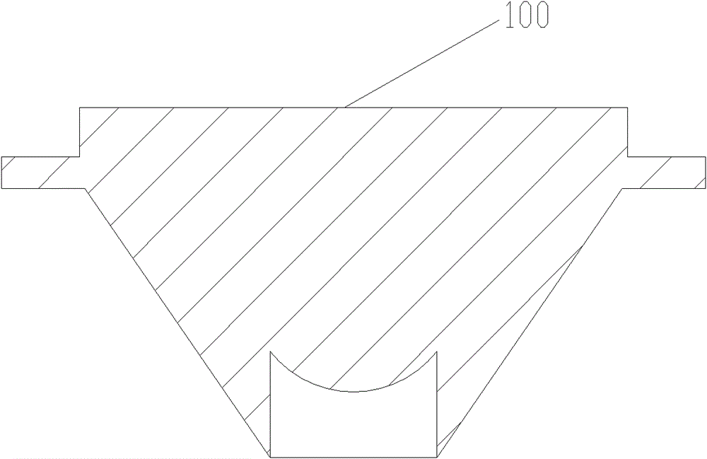
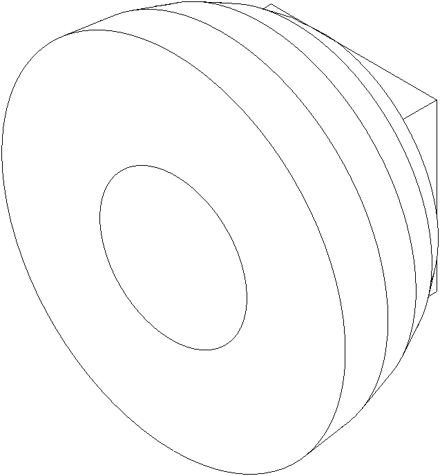
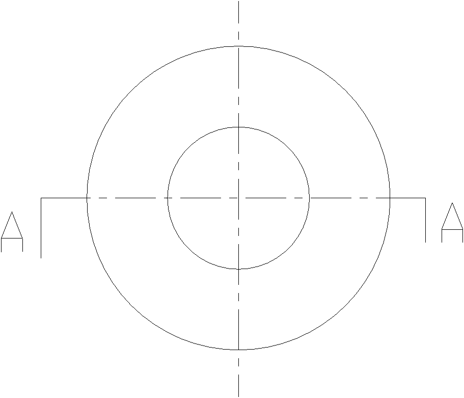
[0034] Such as figure 2 shown, see also image 3 with Figure 4 . In a preferred embodiment of the present invention, the total reflection lens is a revolving body whose revolving generatrix is ​​a broken line, wherein the revolving body's revolving generatrix is ​​formed by successively connecting four line segments, the bottom of which is provided with a light source installation hole, and the center of its light-emitting surface is provided with There is a conical concave surface 3 whose apex falls on the symmetry axis of the total reflection lens. The above-mentioned light source installation hole includes a cylindrical blind hole 1 located at the center of the incident surface of the total reflection lens, and a conical concave hole 2 connected to the cylindrical blind hole 1, wherein the cylindrical blind hole 1 is used for installi...


PUM


Abstract

The invention relates to a floodlight total-reflection lens. The total-reflection lens is a rotary body with a rotary bus as a folding line; the rotary bus of the rotary body is the folding line which is formed by connecting four line sections in sequence; a light source mounting hole is formed on the light incoming surface of the total-reflection lens; a conical concave surface is arranged on the center of the light emitting surface, wherein the peak of the conical concave surface is on the symmetrical shaft of the total-reflection lens; the light source mounting hole comprises a cylindrical blind hole and a conical concave hole formed by extending the cylindrical blind hole inwards; and the symmetrical shaft of the cylindrical blind hole and the symmetrical shaft of the total-reflection lens are overlapped, and the peak of the conical concave hole is on the symmetrical shaft of the total-reflection lens. According to the floodlight total-reflection lens, the rotary bus of the floodlight total-reflection lens adopts the folding line, so that the total-reflection lens meets the requirements of a lighting angle and realizes the floodlight lighting, and simultaneously, the volume is minimized; and the light angle of a light source close to an optical axis can be enlarged through the conical concave surface of the light emitting surface and the bottom conical concave hole, and the lighting uniformity of the lamp in the lighting angle is improved greatly.

Description

technical field [0001] The invention relates to the field of lens technology, and more specifically, to a floodlight total reflection lens and an LED lamp using the lens. Background technique [0002] For LED lights, reflector cups are generally used for light distribution, but this method is not ideal for light type processing, especially the light intensity along the LED optical axis is relatively large, but light distribution through reflectors will always cause low beams The light intensity of the shaft part is high. In addition, there is also a convex lens to concentrate the LED light, but this method has a low utilization rate of the LED luminous flux, which means that the light with a large light-emitting angle of the LED cannot be used, which ultimately leads to a low light efficiency utilization rate of the lamp. At present, there is also a kind of floodlight lens, which is in the LED light-collecting total reflection lens (such as figure 1 Shown), on the basis of...

Claims


Application Information

Patent Timeline
Patent Type & Authority Applications(China)
IPC IPC(8): F21V5/04F21Y101/02
Inventor 周明杰罗英达
Owner OCEANS KING LIGHTING SCI&TECH CO LTD
Why Eureka
Try Eureka