Propeller type surface contour error measurement instrument and method

An error measurement, propeller-type technology, which is applied in the field of propeller profile error measuring instrument and measurement, can solve the problems of inability to meet the requirements of dense point cloud collection, difficult to guarantee the surface accuracy, requiring manual operation, etc., achieving easy and precise control, The effect of improving measurement accuracy and improving measurement efficiency

Active Publication Date: 2012-10-24
HEFEI UNIV OF TECH
View PDF4 Cites 68 Cited by
  • Summary
  • Abstract
  • Description
  • Claims
  • Application Information

AI Technical Summary

Problems solved by technology

The templates used in the template method are all handmade, the surface accuracy is difficult to guarantee, and the rigidity is poor and easy to deform; although the three-coordinate measuring machine has high measurement accuracy, it has high environmental requirements and a small measurement range; the laser tracker has gradually developed in recent years The method and the photoelectric theodolite method can realize high-precision detection of blades. They measure the angle and distance of a single point in the space by the instrument, obtain the three-dimensional coordinates of the target point in real time, and use software to manage and process the data to obtain the spatial geometry of the blade s

Method used


Image

  • Propeller type surface contour error measurement instrument and method
  • Propeller type surface contour error measurement instrument and method
  • Propeller type surface contour error measurement instrument and method

Examples


Embodiment Construction

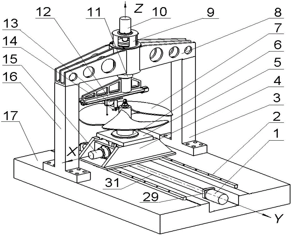
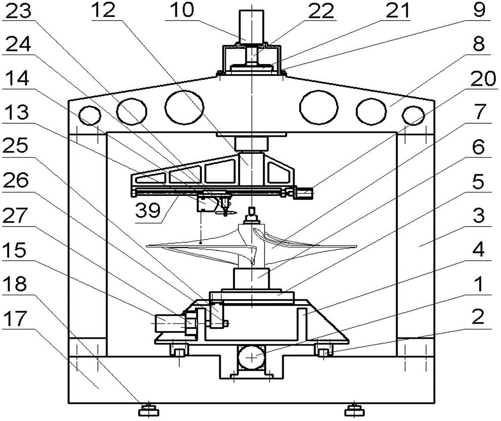
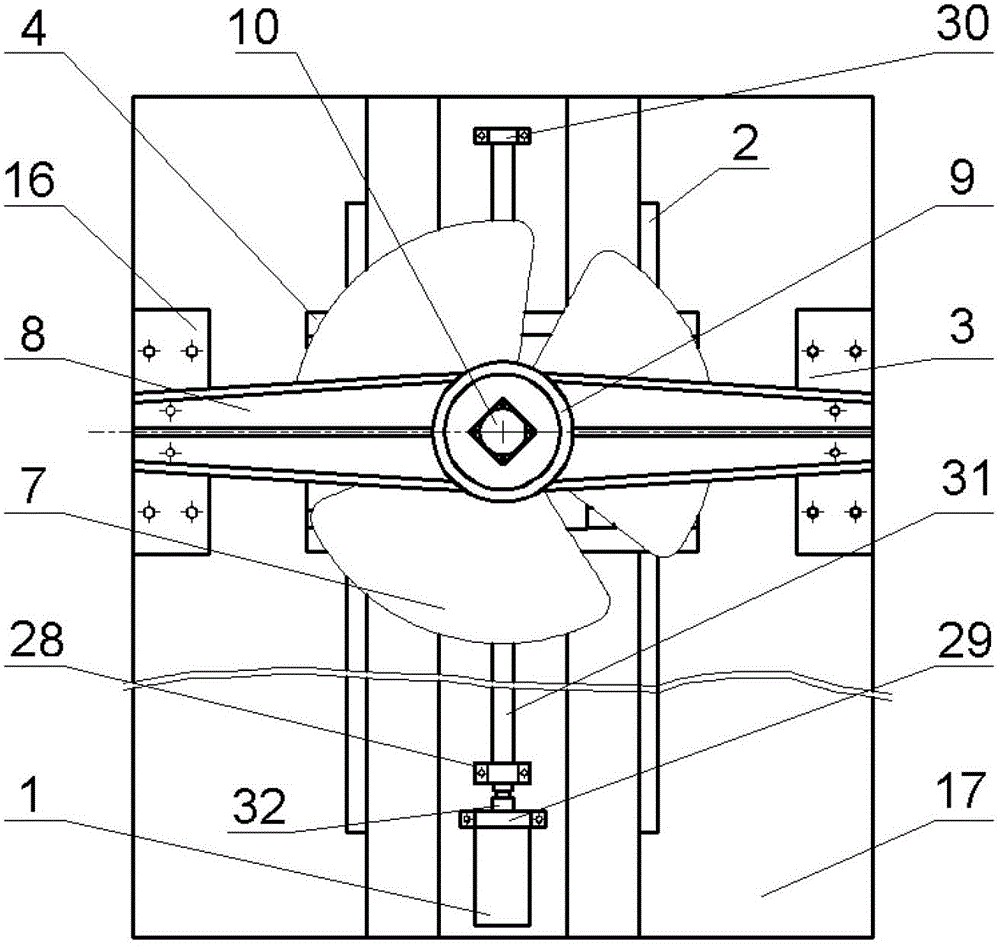
[0047] see figure 1 , figure 2 , The instrument generally adopts a gantry structure, and the granite base 17 is supported on the foundation by eight adjustable feet 18 . On the granite base 17, a left column 16 and a right column 3 of the same height are set, and a beam 8 is erected above the two columns, and a precision rotary spindle 35 is arranged in the middle of the beam 8 along the Z direction, and the first stepper motor 10 passes through the adapter sleeve 9 is fixed on the beam 8, the main shaft of the motor drives the main shaft 35 to rotate through the first flexible coupling 22, and a circular grating 21 for measuring the rotation angle of the main shaft is arranged on the main shaft;

[0048] see figure 2 , Figure 5 and Figure 6 , the measuring arm 12 is fixedly connected to the lower end of the main shaft 35, the measuring arm 12 is arranged perpendicular to the axis of rotation, and the two rotate around the axis Z together. A linear guide rail is set o...


PUM


Abstract

The invention discloses propeller type surface contour error measurement instrument and method. The propeller type surface contour error measurement instrument is characterized in that a gantry structure is adopted, a left upright, a right upright and a top cross beam are arranged on a base, and a revolving spindle is arranged on a cross beam; the lower end of the revolving spindle is horizontally and fixedly connected with a measuring arm; a linear guiderail is arranged on the bottom surface of the measuring arm along the radial direction of the revolving plane of the measuring arm, a working platform capable of doing linear movement along the linear guiderail is arranged on the linear guiderail, and a displacement sensor is arranged on the working platform; and a Y-direction working platform and an X-direction working platform are arranged on the base in an overlapping, and the blade of a detected propeller is arranged in a positioning groove at the top surface of the X-direction working platform. The measuring device and the measuring method are established by adopting a cylindrical coordinate system according to the axial symmetry structure characteristics of the propeller blade. The measuring device and the measuring method are fast in data acquisition, have no objective errors of an operator, and are simple in follow-up error processing and analysis, and can be used for precision measurement on size parameters and geometric error parameters of large revolving parts.

Description

technical field [0001] The present invention relates to a propeller profile error measuring instrument and measuring method, especially suitable for the detection of the propeller blade surface error of large ships and underwater vehicles, and can also be used for steam turbine blades, hydraulic turbine blades, aviation propellers and other large-sized Precision measurement of rotary parts. Background technique [0002] As a widely used propeller, the propeller is the core component of the power system of ships and underwater vehicles. Large mechanical parts with complex surfaces. The processing accuracy of its surface shape is an important factor affecting the service life, mechanical efficiency and noise level of the propeller. However, because its shape is a complex free-form surface, and its volume and weight are large, the measurement of the blade profile and related dimensions and parameters has always been a difficult problem in the industry during the manufacturing...

Claims


Application Information

Patent Timeline
IPC IPC(8): G01B11/24G01B7/28
Inventor 胡鹏浩刘善林胡悦融
Owner HEFEI UNIV OF TECH
Why Eureka
Try Eureka