Supercharge Your Innovation With Domain-Expert AI Agents!

Engine test platform safety protection device

A technology of safety protection device and test bench, which is applied in the field of safety protection device of engine test bench, which can solve the problems of inability to install fuse device and inability to effectively prevent fire, so as to avoid damage and fire, and avoid damage , the effect of improving the utilization rate

Active Publication Date: 2012-10-24
HANGZHOU BRANCH ZHEJIANG GEELY AUTOMOBILE RES INST +2
View PDF6 Cites 1 Cited by
  • Summary
  • Abstract
  • Description
  • Claims
  • Application Information

AI Technical Summary

Problems solved by technology

A short circuit means that the current I is infinite, and the heat energy will increase accordingly, causing a fire. Since the starting current of the starter is about 1000A, and the current maximum fuse capacity is 150A, it is impossible to install a fuse device on the battery line of the bench circuit. This is also a blind spot in automotive circuit design, and it is also a high-incidence point for circuit fires. In order to avoid fires, the engine test bench needs to be installed with a protective device circuit
[0003] In the traditional engine test bench safety protection device circuit, when the electromagnetic switch contacts in the starter are stuck due to some reason (the starter will work for a long time and cause a short circuit of the battery line and cause a fire), the protection device circuit can disconnect the power supply of the starter However, once the engine test bench has a fault such as flames, the device cannot automatically disconnect the main power line of the engine harness and the main power supply of the dynamometer control, so the traditional bench protection device circuit cannot effectively prevent fires.

Method used


Image

  • Engine test platform safety protection device

Examples


Embodiment Construction

[0023] The following are specific embodiments of the present invention and in conjunction with the accompanying drawings, the technical solutions of the present invention are further described, but the present invention is not limited to these embodiments.

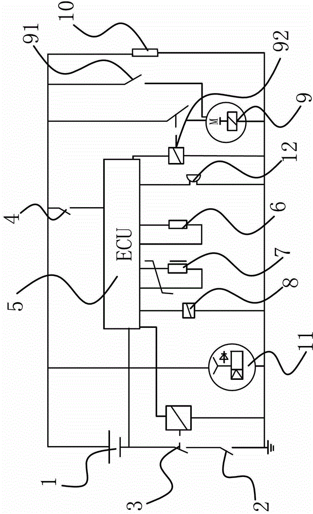
[0024] Such as figure 1 As shown, the engine test bench safety protection device, the engine test bench includes a battery 1, a starter 9 connected to the positive end of the battery 1 and an engine mechanically connected to the starter 9, the engine is mechanically connected to a generator 11 And a dynamometer for detecting engine power, the dynamometer includes a dynamometer electric controller 8 for controlling the work of the dynamometer, the negative terminal of the storage battery 1 is connected with a manual master switch 2, and the protection device includes a The main electromagnetic switch 3 between the battery 1 and the manual switch and the protection device ECU 5 connected to the battery 1, the input end of th...


PUM


Abstract

The invention provides an engine test platform safety protection device, belonging to the technical field of automobiles and solving the problem that the existing protection device can not effectively prevent an engine test platform from fire. The engine test platform safety protection device comprises an electromagnetic main switch connected between a storage battery and a manual switch, and an electronic control unit (ECU) of the protection device connected with the storage battery; an input end of the ECU of the protection device is connected with a flame sensor which is used for detecting a fire source, converting the fire source information into a level signal and transmitting the level signal to the ECU of the protection device; an output end of the ECU of the protection device is respectively connected with an electric controller for a dynamometer, and the electromagnetic main switch; the ECU of the protection device is used for processing the level signal transmitted by the flame sensor; when the level signal is judged to be the level signal of the detected flame, a control signal is output for controlling the electromagnetic main switch to be switched off and controlling the electric controller for the dynamometer to switch off a power supply arranged in the dynamometer. The protection device is high in safety performance and can effectively prevent the occurrence of fire.

Description

technical field [0001] The invention belongs to the technical field of automobiles and relates to a safety protection device for an engine test bench. Background technique [0002] When the engine is running on the test bench, fires often occur. For example, when the engine is working at full speed and full load, the temperature of the exhaust manifold is above 800 degrees. There will be flames on the tube, which will cause a fire. In addition, the aging, short circuit, and overload of the bench circuit are important factors causing fires. Most of the circuit fires come from the battery wires in the bench harness, and the electrical equipment of the engine (except (Except for starting) are matched with fuses, so it can play a protective role, and once the battery line is short-circuited or grounded, it will inevitably discharge with a large current and convert electrical energy into heat energy. The formula: Q=0.24I 2 Rt, from the above formula, it can be concluded that the...

Claims


Application Information

Patent Timeline
Patent Type & Authority Applications(China)
IPC IPC(8): G01M15/02
Inventor 杨辅新付桂龙李慧军由毅赵福全
Owner HANGZHOU BRANCH ZHEJIANG GEELY AUTOMOBILE RES INST
Features
  • R&D
  • Intellectual Property
  • Life Sciences
  • Materials
  • Tech Scout
  • Unparalleled Data Quality
  • Higher Quality Content
  • 60% Fewer Hallucinations
Learn More